Structure of
an Interrupt Handler
I/O
devices and their controllers fall into three major classes.
1. Program
Controlled
2. Interrupt
Driven
3. Direct
Memory Access
Of
these classes, only the latter two can generate interrupts. Here we focus on how the CPU processes the
interrupts associated with such devices.
This lecture focuses on what I
call the “Interrupt Controller Hub”.
This
hub processes interrupts from multiple devices and sends a single INT signal to
the CPU when an interrupt is recognized.
The
CPU sends a single ACK signal back to the hub, which sends it to the
appropriate device.
Interrupt
Priority and CPU Priority
We
follow the design of the PDP–11, developed by the Digital Equipment Corporation
(now defunct) in discussing an interrupt structure.
We
begin with the idea of a CPU execution priority. This is specified by a 3–bit number in the
program status register (PSR). Here is
the structure that we shall use.
|
Bits |
15 – 8 |
7 |
6 |
5 |
4 |
3 |
2 |
1 |
0 |
|
Use |
Other Uses |
N |
Z |
V |
C |
I |
CPU Priority |
||
We postulate a 16–bit
program status register with the following bits:
N, Z, V, & C Status of the previous arithmetic
operation
(Always
included in the PSR, so we use these too)
I Interrupts enabled.
When
I = 0, the CPU ignores any interrupt.
Priority A 3–bit unsigned integer representing the CPU
execution
priority.
The I Bit
and CPU Execution Priority
These
four bits are used in processing interrupts.
Disabling Interrupts (I = 0)
This
should be done very seldom. Only the
Operating System can set the I bit.
There
are certain times in processing an interrupt during which another interrupt
cannot be processed. During these short
times, the CPU sets I = 0.
CPU Priority
Normal
programming practice allows for multiple interrupt priorities and nested
interrupts. A high priority device, such
as a disk, can take precedence over the processing of an interrupt for a low
priority device, such as a keyboard.
To
manage devices at various priorities, each interrupt is processed as follows.
1. A
device interrupts with priority K.
2. The
CPU sets I = 0 and saves various registers.
3. The
CPU sets its priority to K (the same number), sets I = 1,
and then begins execution
of the interrupt handler.
Devices
with higher priorities can now interrupt and have their interrupts handled.
More on CPU
Priority
We
follow the PDP–11 convention.
Priority
= 0 All user programs
execute at this level.
Priority
= 1, 2, 3 Various Operating
System Utilities operate at these levels.
We
generally ignore these levels.
Priority
= 4, 5, 6, 7 Interrupt handlers
operate at these levels.
The
CPU will acknowledge and process an interrupt only if the priority of the
interrupting device is higher than the CPU execution priority.
For
this reason, almost all interrupt handlers are written to execute with a CPU
priority exactly equal to the device priority.
The
convention is that all hardware devices are assigned one of four interrupt
levels:
4, 5, 6, and 7.
Priority 4 is the lowest hardware priority, reserved for the keyboard,
etc.
Priority 7 is the highest hardware priority, reserved for disks, etc.
Vectored
Interrupts
How
does the CPU identify the device that asserted the interrupt and begin
execution of its interrupt handler? More
on this later, but for now:
1. The device sends its “vector”, which is an
address of a data structure.
This is most often an address in
low memory, say addresses 0 – 1023.
2. The data structure at the specified address
contains the following.
a) The
address of the interrupt handler associated with the device.
b) The
CPU execution priority for the interrupt handler.
The interrupt handling sequence
can be elaborated.
1. Clear the Interrupt Enabled bit (set I = 0)
to block other interrupts.
2. Store the essential registers, so that the
user program can be restarted later.
3. Load the PSR with the execution priority
and load the PC with the address.
4. Set I = 1 to allow nested interrupts and start
execution of the handler.
Interrupt Lines
and Assertion Levels
The
structure of the interrupt lines on our computer is as follows:
We
have four interrupt lines, one for each of the four priority levels.
Each is paired with an acknowledge line for the same priority.
Interrupts
are asserted low; that is, the
signal goes to 0 when the device interrupts.
Acknowledgements
are asserted high; that is, the
signal goes to logic 1 to acknowledge.
Mechanism
for Asserting an Interrupt
Each
interrupt line is attached to a “pull down” resistor.
When
the device asserts an interrupt, it sets its Interrupt Flip–Flop. Thus Q = 1.
This enables the tri–state, which becomes a closed switch with very low
resistance.
With
the tri–state enabled, all the voltage drop is across the resistor so that the
voltage on the Interrupt Line becomes 0.
The interrupt is asserted.
With
the tri–state disabled, it becomes an open switch, a line with very high
resistance.
All the voltage drop is across the tri–state, so the Interrupt Line stays at
voltage.
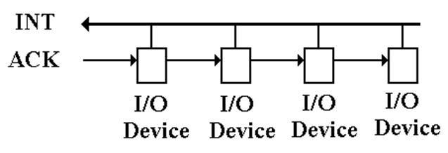
Multiple
Devices on One Line
By
design, Interrupts are active low in order to facilitate attaching multiple
interrupting devices on a single interrupt line.
Here
we see four devices attached to a single line.
If
no device is interrupting, we have Int = Logic 1
If
any one device is interrupting, we have Int = Logic 0. The interrupt is asserted.
If
more than one device is interrupting, we still have Int = Logic 0.
The devices cannot interfere with each other.
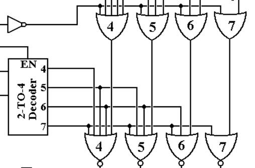
The Big
Picture
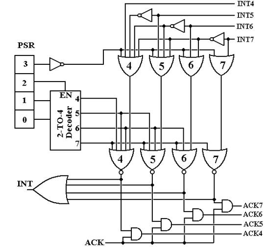
Here
is the entire circuit for the controller hub.
The Hub:
Part 1
Look
first at the output of the PSR.
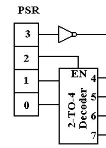
If
PSR3 = 0, the output of the not gate is 1. We see later how this disables interrupts.
If
PSR2 = 0, the CPU execution priority is less than 4. This is less than the priority
of any I/O device.
If
PSR2 = 1, the output of the 2–to–4 decoder indicated the CPU
execution priority,
which must be in the range
4 to 7 inclusive.
The Hub:
Part 2
Remember
that interrupts are asserted low. This
circuit has at most one of its outputs equal to 0. The rest are 1. Possibly all are logic 1.
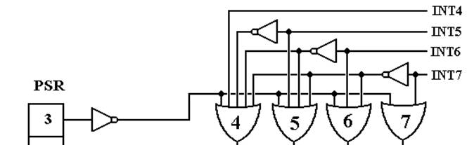
If
PSR3 = 0, the input from the left is logic 1, and the output of each
of the four OR
gates is also 1. No interrupt is recognized.
If
all of Int4, Int5, Int6 and Int7 are logic 1 there is no interrupt being
asserted.
The output of each of the
four OR gates is also 1 and no interrupt is recognized.
Suppose
Int7 = 1 and Int6 = 0. The output of OR
gate 7 is 1. The output of OR gate 6
is logic 0. Since the negation of Int6 goes into OR gates
4 and 5, the output of
each of those gates is 1. Thus only one gate has a logic 0 output.
The Hub:
Part 3
At
this point, either all of the OR gates at the top are outputting a logic 1,
or exactly one has output of logic 0.
The
NOR gates at the bottom are a key point of converting the active low device
interrupt to an active high acknowledgement signal.
If
all OR gates output a logic 1, each of the NOR gates will output a logic 0.
No acknowledgement will be generated.
The Hub:
Part 4
We
now consider what happens when exactly one of the OR gates at the top has an
output of logic 0. Say that OR gate 5
has an output of logic 0.

Each
of NOR gates 4, 6, and 7 will have an output of 0.
NOR
gate 5 will have an output of logic 1 if and only if all of its inputs are
0. Look at the decoder. This will occur only if the CPU priority is less
than 5.
The Hub:
Part 5
We
now have one of two cases:
1. The
output of all the NOR gates is 0, so INT = 0 and nothing happens.
2. The
output of exactly one NOR gate is 1, so INT = 1 and the CPU is signaled.
Say that NOR gate 5 has an
output of logic 1.
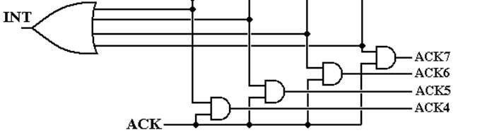
When
the CPU can process the interrupt, it asserts its single ACK signal high.
Thus ACK = 1.
We
still have the output of NOR gate 5 at 1, so we generate Ack5 = 1.
We also have Ack4 = 0, Ack6 = 0, and Ack7 = 0.
Situation: One or more device at level 5
has interrupted. Ack5 is asserted.
No device at level
6 or 7 has interrupted.
We have no
information about level 4.
Daisy
Chaining
In
daisy chaining, the ACK is passed from device to device until it hits a device
that has asserted an interrupt.
If
the I/O device has not asserted an interrupt, it passes the ACK to the
next “downstream” I/O device.
Priority
rank is by physical proximity to the CPU.
Daisy
Chaining (Part 2)
The
ACK is passed down the line to the first I/O device attached.
If
that device has not raised an interrupt, it passes the ACK to the next device.
When a device that asserted an interrupt gets the ACK, it captures it and does
not pass it.