Sequencing
the Major State Register
Recall
that the hardwired control unit is based on two interrelated registers:
the Minor State Register and the Major State Register.
The
Minor State Register is a modulo–4 counter, producing the sequence
T0, T1, T2, and T3 continuously while the computer is running.
T3
from the Minor State Register is the trigger for the Major State Register to
change.
This causes the Major State Register to accept control input and possibly
change on the rising edge of the T0 pulse.
The
possible sequences of the Major State Register follow three patterns
1. Fetch
to Fetch
2. Fetch
to Execute
3. Fetch
to Defer to Execute
The
sequencing of the Major State Register depends on two control signals generated
by the control unit. These are called S1
and S2.
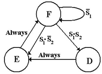
The State
Diagram for the Major State Register
Here
is the state diagram for the register.
It has three states: F, D, and E.

The
two control signals S1 and S2 control the sequence of
this register.
If
the present state is Fetch (F) then
If S1 = 0, the next major
state will be Fetch.
If S1 = 1 and S2 =
0, the next major state will be Execute.
If S1 = 1 and S2 =
1, the next major state will be Defer.
If
the present state is Defer (D), the next state will be Execute.
If
the present state is Execute (E), the next state will be Fetch.
Sequencing
the Major States: Observations on the ISA
Recall
that 14 of the 22 instructions in the ISA complete execution in Fetch.
Of
the eight instructions that require the Execute state, only four can enter
Defer.
The
next table examines these eight instructions.
|
|
IR31 |
IR30 |
IR29 |
IR28 |
IR27 |
IR26 = 0 |
IR26 = 1 |
|
GET |
0 |
1 |
0 |
0 |
0 |
Execute |
|
|
PUT |
0 |
1 |
0 |
0 |
1 |
Execute |
|
|
RET |
0 |
1 |
0 |
1 |
0 |
Execute |
|
|
RTI |
0 |
1 |
0 |
1 |
1 |
Execute |
|
|
LDR |
0 |
1 |
1 |
0 |
0 |
Execute |
Defer |
|
STR |
0 |
1 |
1 |
0 |
1 |
Execute |
Defer |
|
JSR |
0 |
1 |
1 |
1 |
0 |
Execute |
Defer |
|
BR |
0 |
1 |
1 |
1 |
1 |
Execute if Branch = 1, Fetch Otherwise |
Defer if Branch = 1, Fetch Otherwise |
Two
patterns become obvious.
1. Only instructions with IR31 = 0
and IR30 = 1 can leave Fetch
2. Only instructions with IR31 = 0,
IR30 = 1, IR29 = 1, and IR26 = 1 can enter
Defer.
Generation
of the S1 Control Signal
We note the following about the generation of the S1
control signal.
1. S1 is 0 when IR31IR30
¹ “01”.
For
this reason, we say S1 = ![]() · (Something else).
· (Something else).
2. If IR31IR30 = “01”,
then S1 is 0 when if Branch = 0 and IR29IR28IR27
= “111”.
Put
another way, IR31IR30 = “01”, then S1 is 1
when either
a) Branch = 1, or
b) IR29IR28IR27
¹ “111”. This is equivalent to ![]() = 1.
= 1.
So we have the following for the S1 control
signal.
S1 = ![]() ·(Branch +
·(Branch + ![]() ).
).
Condition
2 addresses the Branch instruction when the branch condition is not met.
Generation
of the S2 Control Signal
Generation
of the S2 control signal is simplified by the fact that it is used
only
in combination with the S1 control signal.
Technically
we should say that S2 = ![]() · IR29 · IR26.
· IR29 · IR26.
However
the first part is handled by the S1 control signal, so S2
= IR29 · IR26.
Again, here is the state
diagram for the Major State Register.
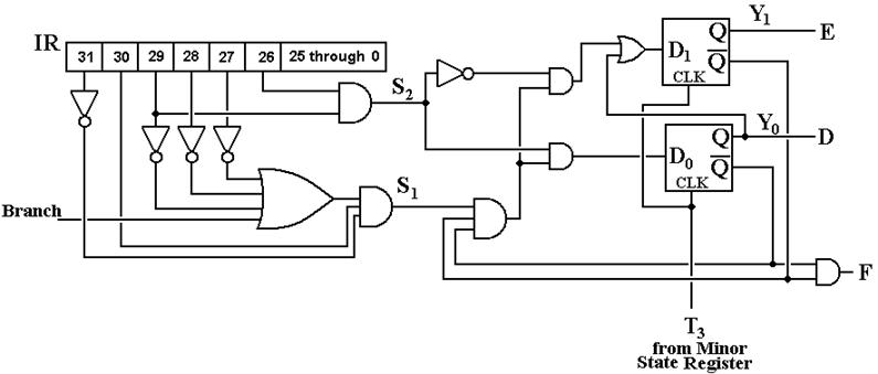
Design of
the Major State Register
The
Major State Register is implemented by two D flip–flops, D1 and D0.
The
inputs to these flip–flops are derived from the major state and the signals S1
and S2.
The
trigger for the state transitions is the T3 pulse from the Minor State
Register.
The binary encoding for the
major states is shown in the following table.
|
State |
Y1 |
Y0 |
|
F |
0 |
0 |
|
D |
0 |
1 |
|
E |
1 |
0 |
We
note that the circuit, when operating properly, never has both D1 =
1 and D0 = 1.
Thus we may say that D1 =
conditions to move to Execute
D0 = conditions to move to
Defer
This
gives rise to the following equations.
D0 = F·S1·S2 //
F = 1 if and only if the major state is Fetch
D1 = ![]() + D // D = 1 if and only if the major
state is Defer
+ D // D = 1 if and only if the major
state is Defer
Circuitry
for the Major State Register
Here
it is.
Impact of
the Major State Register on ISA Design
The
Boz–5 has had four different allocations of numeric codes to the assembly
language instructions. Each of the three
revisions was done to simplify the Major State Register.
|
Op-Code |
|
Version 1 |
|
Version 2 |
|
Version 3 |
|
Version 4 |
|
00 000 |
|
HLT |
|
HLT |
|
HLT |
|
HLT |
|
00 001 |
|
LDI |
|
LDI |
|
LDI |
|
LDI |
|
00 010 |
|
ANDI |
|
ANDI |
|
ANDI |
|
ANDI |
|
00 011 |
|
ADDI |
|
ADDI |
|
ADDI |
|
ADDI |
|
00 100 |
|
GET |
|
|
|
|
|
|
|
00 101 |
|
PUT |
|
|
|
|
|
|
|
00 110 |
|
LDR |
|
|
|
|
|
|
|
00 111 |
|
STR |
|
|
|
|
|
|
|
01 000 |
|
BR |
|
GET |
|
GET |
|
GET |
|
01 001 |
|
JSR |
|
PUT |
|
PUT |
|
PUT |
|
01 010 |
|
RET |
|
LDR |
|
RET |
|
RET |
|
01 011 |
|
RTI |
|
STR |
|
RTI |
|
RTI |
|
01 100 |
|
|
|
BR |
|
LDR |
|
LDR |
|
01 101 |
|
|
|
JSR |
|
STR |
|
STR |
|
01 110 |
|
|
|
RET |
|
BR |
|
JSR |
|
01 111 |
|
|
|
RTI |
|
JSR |
|
BR |
NOTE: Version 1 is just a listing in the order I
thought of the instructions.
Modifications
of the ISA Order
Version 2
This
numbering leads to the simplification that only instructions with
IR31 = 0 and IR30 = 1 can enter either the Defer or
Version 3
Moving
the RET and RTI instructions to follow GET and PUT yields the
structure that only instructions with IR31 = 0, IR30 = 1,
and IR29 = 1 can enter Defer.
Version 4
A
minor reordering to yield the condition (Branch + ![]() ) for S1.
) for S1.
Here
is the ISA structure achieved for Versions 3 and 4.
|
IR31 |
IR30 |
IR29 |
Result |
|
0 |
0 |
d |
Executes in the Fetch cycle |
|
0 |
1 |
0 |
Executes in Fetch and
Execute, cannot enter Defer |
|
0 |
1 |
1 |
Executes in Fetch and
Execute, may enter Defer |
|
1 |
d |
d |
Executes in the Fetch cycle |