Structure of
the Arithmetic–Logic Unit
We begin by again listing the major functions of the
ALU and matching the
inputs required by each of these functions to the input bus structure.
The functions are
add Need
to perform addition. Supports the ADD
instruction. Updates the PC.
tra1 Transfer
bus B1 contents to bus B3
tra2 Transfer
bus B2 contents to bus B3.
shift Needed
to activate the barrel shifter
not Needed
to support the assembly language instruction NOT.
sub Needed
to support the subtract instruction SUB.
or Needed
to support the assembly language instruction OR.
and Needed
to support the assembly language instruction AND.
xor Needed
to support the assembly language instruction XOR.
The
allocation of source busses for each operation is shown below.
|
Source |
tra1 |
tra2 |
shift |
not |
add |
sub |
or |
and |
xor |
|
B1 |
X |
|
|
|
X |
X |
X |
X |
X |
|
B2 |
|
X |
X |
X |
X |
X |
X |
X |
X |
Major
Functional Units of the ALU
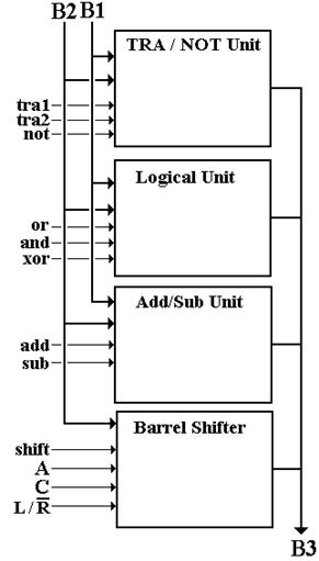
Here is the top–level structure of the ALU.
It has four major functional units, each labeled by
the function that the unit performs.
The TRA/NOT unit handles transfers from B1 to B3,
B2 to B3, and the logical NOT function.
The logical unit handles the dyadic Boolean functions.
The Add/Sub unit handles addition and subtraction,
using a single adder that is modified to handle subtraction. This design calls for a ripple–carry adder,
which is extremely inefficient.
The barrel shifter unit handles all shifts.
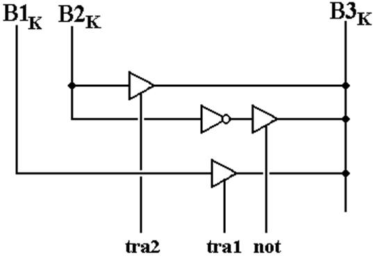
The TRA/NOT
Unit
This is very simple.
It contains the following circuit, replicated 32 times,
once for each of the 32 bits.
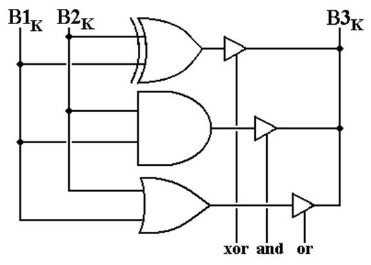
The Logical
Unit
This is also very simple. It contains the following circuit, replicated
32 times,
once for each of the 32 bits.
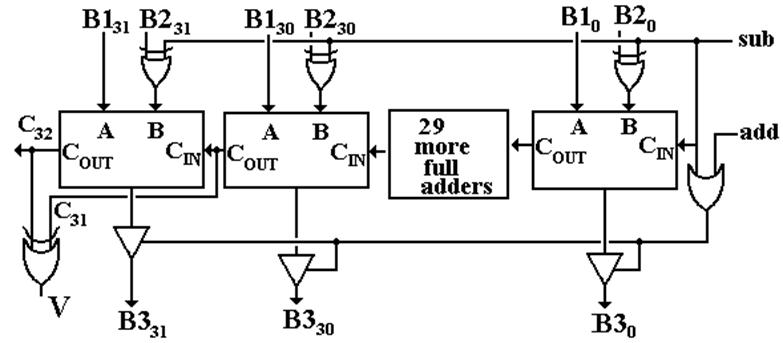
The
Add/Subtract Unit
Any reasonable design would use more advanced adders,
with carry–lookahead circuitry.
Our extremely simple design uses a ripple–carry adder.
The Barrel
Shifter
The barrel shifter is called a logarithmic unit in
that it has log232 = 5 stages, one for shifts by 1 bit, one for
shifts by 2, one for shifts by 4, etc.
Each bit in the shift count activates one of the shift
levels.