Instruction
Set Architecture (ISA) of the Boz–5
This
chapter of the textbook begins a three–chapter sequence on the design of a
“didactic computer” called the Boz–5, the 5th design by your
instructor.
The
design is called “didactic” because many of its features exist only
to be used within a context of teaching.
The
Boz–5 shares many RISC characteristics, including being a Load–Store
design, but retaining some CISC characteristics as well.
The
Boz–5 is a stored program computer, following the von Neumann model.
It is a fetch–execute design with no pipelining and few modern features.
Topics
for the ISA include:
1. The
general–purpose register set and its use
2. The
special–purpose registers, including the PSR, and their use.
3. The
address space and management of memory
4. The
handling of the Input/Output devices (I/O)
Specification
of the Boz–5
1) It
is a stored program computer; i.e., the computer memory is used to
store both data and the
machine language instructions.
2) It
is a Load/Store machine; only register loads and stores access
memory. All arithmetic and logic operators are done
on registers.
3) The
Boz–5 is a 32–bit machine. The basic
unit of data is a 32–bit
word. This is in contrast to machines, such as the
Pentium class, in
which
the basic data unit is the byte (8 bits).
4) This
is a two’s-complement machine. Negative
numbers are stored in
the two’s-complement
form. The range for integer values in
from
– 2,147,483,648 to
2,147,483,647 inclusive.
5) Real
number arithmetic is not supported. We
may envision the
computer as a typical RISC,
with an attached floating point unit that we
will not design.
6) The
CPU uses a 26–bit Memory Address Register (MAR) to address
memory. This implies 226 words (64 M
words) of main memory.
Cache memory is not used.
Specification
of the Boz–5 (Part 2)
7) The
memory uses a 32–bit Memory Buffer Register (MBR) to transfer
data to and from the Central
Processing Unit. The MBR is used by
Instruction Fetch to
transfer instructions to the CPU.
8) The
Boz–5 uses isolated I/O with the dedicated instructions GET and
PUT, each of which takes an
address on the I/O bus as an argument.
9) The
CPU uses a 16–bit I/O Address Register (IOA) to address I/O
registers. This implies 216 = 65,536
registers associated with I/O.
10) The
CPU uses a 32–bit I/O Data Register (IOD) to put and get I/O data.
11) The
Boz–5 uses 20-bit addressing and the entire address space is
occupied. The memory is 32–bit word-addressable, for a
total of 220
(1 048 576) words. It is not
byte–addressable. One advantage of this
addressing scheme is that we
may ignore the byte ordering problem
known as Big Endian – Little
Endian.
12) The
Boz–5 has a 5–bit op-code, allowing for a maximum of 25 = 32
different instructions. As yet, not all op-codes have been assigned.
Specification
of the Boz–5 (Part 3)
13) The
Boz–5 has four addressing modes: direct, indirect, indexed, and
indexed-indirect. In addition, two instructions explicitly call
for
immediate addressing, in
which the operand is in the instruction itself.
Indexed-indirect addressing
is implemented as pre-indexed indirect.
This decision allows
implementation of register indirect addressing,
a fifth address mode.
14) The
Boz–5 has eight general purpose registers, denoted %R0 through
%R7, with the “%” prefix
indicating a general–purpose register.
Each of these registers is a
32–bit register, able to hold a complete
memory word.
%R0 is identically 0. It stores only the constant 0 and is not
changed.
%R1 through %R7 is
read/write registers, used to store results of
computation.
Each of the eight registers
can be used as an index register or as the source operand for an
instruction. Only registers %R1 – %R7
can be changed by arithmetic or register load operations. Attempts to change %R0 are undertaken for
side effects only, such as setting the ALU status flags in the PSR.
Structure of
the Memory Address Space
The
physical memory of the Boz–5 is quite small, comprising only 64 M words, which
is 67,108,864 32–bit words or 256 megabytes.
It is not byte addressable.
The
MMU (Memory Management Unit) breaks the memory into 64 pages of
1 M word (1, 048, 576 words) each.
Each
executing process, except the Operating System, is allocated exactly one page
of physical memory and cannot generate addresses outside that page.
The
mapping of logical addresses to physical addresses is achieved as follows:
Physical_Address = (Page Number)·220 + Logical_Address
All
processes, including the Operating System, view the MAR as a 20–bit register
that generates a 20–bit logical address.
The
Operating System executes in page 0, but has the privilege to change its page
number so that it can access any physical address in memory.
The goals of this strange
design are:
1) To
introduce a simple memory management system,
2) To
motivate discussion of simple Operating System security.
Operation of
the Memory Management Unit
The
MMU takes the address part of the IR and the page bits in the PSR to
generate an address.
The
address part of the Instruction Register is IR19–0, the low order 20
bits.
The
page number is found in bits 21–16 of the PSR.
The
26–bit address is formed by concatenation, which has the same effect as
multiplication followed by addition.
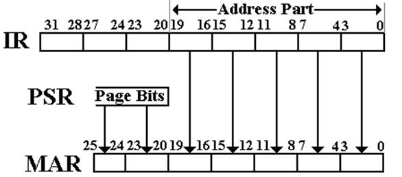
Shifting
the page bits left by 20 bits is the same as multiplication by 220.
The Program
Status Register (PSR)
The
PSR (Program Status Register) of the Boz–5 is a 32–bit word.
It
contains Boolean flags and bit fields to control the status of the CPU.
All
of the bits in the PSR can be read by any program, User or O/S.
The
write status of these bits varies by function.
The
ALU status bits (V, C, Z, and N) are set directly by ALU actions.
No programs (O/S or User) can write directly to these bits.
The
O/S can write to the other bits and does so in order to manage execution of I/O
and User processes. In particular, it
uses some fields as follows:
The CPU priority to match execution priority to the I/O device priority
The I bit to
turn off interrupts until they can be handled safely
Security Flags to grant each program appropriate access rights.
The Page Number to allocate a page of memory to a user process.
to
change the range of addresses it can access.
The PSR
(Part 2)
Here
is the layout of the PSR.
|
31 |
30 |
29 |
28 |
27 |
26 |
25 |
24 |
23 |
22 |
21 |
20 |
19 |
18 |
17 |
16 |
|
Not
presently assigned. |
6–bit
Page Number |
||||||||||||||
The ten bits marked “not
presently assigned” are reserved for future options for support of the
Operating System. Software designers who
give in to the temptation to use these ten spare bits for other purposes might
get a surprise when these bits are assigned by the hardware architect. This has happened.
|
15 |
14 |
13 |
12 |
11 |
10 |
9 |
8 |
7 |
6 |
5 |
4 |
3 |
2 |
1 |
0 |
|
Security
Flags |
V |
C |
Z |
N |
R
= 00 |
I |
CPU
Priority |
||||||||
The security flags are
yet to be determined. They are mentioned
here as a part of your author’s campaign for more effective hardware support of
security.
The I/O design will call for
eight priority levels for interrupts; thus three bits to specify CPU
priority. The control unit design is
facilitated by grouping the I bit and 3 priority bits as the four low–order
bits of the PSR.
More On
Handling Interrupts
At
any given time, the CPU is executing with a given priority, P(CPU).
For user programs, normally P(CPU) = 0.
P(CPU) is stored in the PSR.
At
any given time, either interrupts are enabled (I = 1) or disabled (I = 0).
Each
I/O device is assigned an interrupt priority, P(DEV).
All
hardware interrupts are handled by an Interrupt Handler, which issues a general
interrupt signal, INT, to the CPU only when:
1. A
device interrupts,
2. P(DEV)
> P(CPU), and
3. I
= 1.
The
normal CPU response to the general INT signal is as follows.
1. Set
I = 0 to disable further interrupts until this one can be identified.
2. Determine
the source of the interrupt and its priority.
At this point, we know that
P(DEV) > P(CPU).
3. Schedule
the interrupt handler to be run. Set
P(CPU) = P(DEV)
and set I = 1.
4. Run
the device handler for the I/O device.
Data Formats
in the Boz–5
Each
word in the Boz–5 has 32 bits, numbered left to right as 31 through 0.
Bit 31 is the most significant bit; bit 0 is the least significant bit.
Character Data Format
8–bit
characters (ASCII)
|
Bits |
31 to 24 |
23 to 16 |
15 to 8 |
7 to 0 |
|
Character |
3 |
2 |
1 |
0 |
16–bit
characters (Unicode)
|
Bits |
31 to 16 |
15 to 0 |
|
Character |
1 |
0 |
Integer Data Format
Thirty–two
bit two’s complement arithmetic is used, leading to a range from
– (231) to (231 – 1) or – 2,147,483,648 to 2,147,483,647
inclusive.
Real Number Format
Real
numbers and other data formats are not supported by this simple CPU.
The Assembly
Language of the Boz–5
The
Boz–5 uses bits 31 – 27 of the IR as a five–bit opcode.
Of
the possible 32 opcodes, only 26 are implemented.
|
Op-Code |
Mnemonic |
Description |
|
00000 |
HLT |
Halt
the Computer |
|
00001 |
LDI |
Load
Register from Immediate Operand |
|
00010 |
ANDI |
Logical
AND Register with Immediate Operand |
|
00011 |
ADDI |
Add
Signed Immediate Operand to Register |
|
00100 |
NOP |
Not
Yet Defined – At Present it is does nothing |
|
00101 |
NOP |
Not
Yet Defined – At Present it is does nothing |
|
00110 |
NOP |
Not
Yet Defined – At Present it is does nothing |
|
00111 |
NOP |
Not
Yet Defined – At Present it is does nothing |
This
strange gap in the opcodes caused by not using 4, 5, 6, and 7 will be seen to
facilitate the design of the control unit.
More Opcodes
Here
are the opcodes in the range 8 to 15.
|
Op-Code |
Mnemonic |
Description |
|
01000 |
GET |
Input
to Register |
|
01001 |
PUT |
Output
from Register |
|
01010 |
RET |
Return
from Subroutine |
|
01011 |
RTI |
Return
from Interrupt (Not Implemented) |
|
01100 to 01111 |
NOP |
Not Yet Defined – At
Present these do nothing |
The Last
Opcodes
|
Op-Code |
Mnemonic |
Description |
|
01100 |
LDR |
Load
Register from Memory |
|
01101 |
STR |
Store
Register into Memory |
|
01110 |
JSR |
Subroutine
Call |
|
01111 |
BR |
Branch
on Condition Code to Address |
|
10000 |
LLS |
Logical
Left Shift |
|
10001 |
LCS |
Circular
Left Shift |
|
10010 |
RLS |
Logical
Right Shift |
|
10011 |
RAS |
Arithmetic
Right Shift |
|
10100 |
NOT |
Logical
NOT (One’s Complement) |
|
10101 |
ADD |
Addition |
|
10110 |
SUB |
Subtraction |
|
10111 |
AND |
Logical
AND |
|
11000 |
OR |
Logical
OR |
|
11001 |
XOR |
Logical
Exclusive OR |
Privileged
Instructions
In
modern computer design, certain instructions are not available to programs
executing in User Mode. The assembler
will translate these into Traps, which are requests to the Operating System for
it to do something.
Here
are the Boz–5 instructions that should be privileged.
HLT Stop
the Computer
This will be
translated into a return to Operating System control.
The operating system
will terminate program execution, resume
control, and pass
the execution to another program.
GET Input
directly from a physical device.
This will be
translated into a Trap to the O/S input routine.
PUT Output
directly to a physical device.
This will be
translated into a Trap to the O/S output routine.
Addressing
Modes
The
Boz–5 uses a number of modes to generate memory addresses. For this discussion, a direct reference to a
general–purpose register, such as used by the arithmetic instructions, will not
be called an addressing mode.
We
shall devote a lecture to addressing modes.
For the moment, we shall give the names of these modes and define
one. The modes are:
1. Immediate
2. Direct
3. Indirect
4. Indexed
5. Indexed
Indirect
6. Register
Indirect
These
six addressing modes are a bit too many for a pure RISC design, but do not
compare with the twenty or more seen in a fully CISC design.
Immediate
Addressing
It
is convenient and good design practice to encode some small arguments directly
into the assembly language instruction.
The
Boz–5 has three instructions with immediate arguments.
LDI Load
the register with the immediate argument,
ANDI Mask
the register with the immediate argument, and
ADDI Add
an immediate argument to the register.
In
immediate addressing, the twenty low–order bits of the instruction,
stored in bits 19 – 0 of the IR, are used to hold a constant.
For
the ANDI, the 20 bits are viewed as a bit mask and not an integer value.
This mask is represented as five hexadecimal digits.
As a result of the ANDI, the high–order 12 bits of the register are changed to
0.
For
the LDI and ADDI, this constant is viewed as a 20–bit two’s–complement integer,
having values in the range – (219) to (219 – 1), or –
524, 288 to 524, 287.
The
most common immediate arguments will be – 1, 0, and + 1. The unusually large range in the Boz–5 is a
result of a desire to keep the control unit simple.
Immediate
and Direct Addressing
To
clarify the idea of immediate addressing, we investigate three instructions.
LDI Load
Register Immediate
LDR Load
Register from Memory
STR Store
Register into Memory
Consider
the following instructions:
LDI %R1, 100 Load the value 100 into register R1
LDR %R1, 100 Load the contents of memory location 100
into
register R1; R1 ¬ M[100].
STR %R2, 100 Store the contents of register R2 into memory
location
100; M[100] ¬ (R2).
There
is no such thing as a Store Immediate instruction.
Direct
Addressing: Memory vs. I/O
The
Boz–5 uses isolated I/O, in which there are two address spaces.
A 20–bit address space for memory
references, and
A 16–bit address space for I/O
references.
Consider
the following two instructions:
LDR %R3,
200 Load register R3 from
memory location 200.
R3
¬ M[200]
GET %R3,
200 Load register R3 from the
32–bit I/O device
register
at address 200 on the I/O bus.
For
simplicity of design, all references to I/O device registers will use
direct addressing only.
NOTE: Some I/O registers are read–only. Attempts to write to these registers,
using a PUT instruction will
have no effect.
Basic
Structure of Memory Addressing
The
memory addressing modes are built around two basic ideas.
Indirection the memory location contains an address.
This is similar to
the use of pointers in a modern HLL.
Indexing: the memory address is modified by an index.
This is a direct
implementation of a one–dimensional array.
Indirection
and indexing can be combined in two distinct ways.
Pre–Indexed the indexing is done first, then the
indirection.
Think of an
array of pointers.
Post–Indexed the indirection is done first, then the
indexing.
Think of a
pointer to an array, or an array passed by reference.
These two basic ideas generate
four basic addressing modes.
|
|
Indexing Not Used |
Indexing Used |
|
Indirection Not Used |
Direct Addressing |
Indexed Addressing |
|
Indirection Used |
Indirect Addressing |
Indexed-Indirect Addressing |
Immediate addressing does not
fit into this scheme.