Modulo–4
Up–Down Counter
This
is a counter with input.
If X = 0,
the device counts up: 0, 1, 2, 3, 0, 1, 2, 3, etc.
If X = 1, the device counts down: 0, 3, 2, 1, 0, 3, 2, 1, etc.
Step 1a: Derive the state diagram and state table for
the circuit.
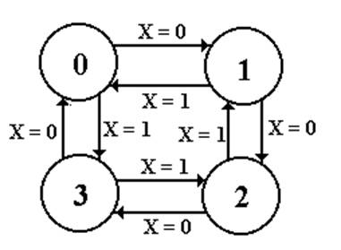
Note
two transitions between the state pairs: one is up and one is down.
Step 1b: Derive
the State Table
|
Present State |
Next State |
|
|
|
X = 0 |
X = 1 |
|
0 |
1 |
3 |
|
1 |
2 |
0 |
|
2 |
3 |
1 |
|
3 |
0 |
2 |
This
is just a restatement of the state diagram.
Note:
Two columns for the “Next State”.
Step 2:
Count the States and
Determine the Flip–Flop Count
Count the States
There
are four states for any modulo–4 counter. N = 4
The
states are simple: 0, 1, 2, and 3.
Calculate the Number of Flip–Flops
Required
Let
P be the number of flip–flops.
Solve
2P-1 < N £ 2P. So 2P-1
< 4 £ 2P and P = 2.
We
need two flip–flops.
Step 3: Assign
a unique P-bit binary number
(state vector) to each state.
Here
P = 2, so we are assigning two–bit binary numbers.
Vector
is denoted by the binary number Y1Y0.
|
State |
2-bit Vector |
|
|
Y1 Y0 |
|
0 |
0 0 |
|
1 |
0 1 |
|
2 |
1 0 |
|
3 |
1 1 |
Each state has a unique
2–bit number assigned.
Any
other assignment would be absurd.
Step 4: Derive
the state transition table
and the output table.
There
is no computed output, hence no output table.
The
state transition table uses the 2–bit state vectors
|
Present State |
Next State |
||
|
|
|
X = 0 |
X = 1 |
|
0 |
00 |
01 |
11 |
|
1 |
01 |
10 |
00 |
|
2 |
10 |
11 |
01 |
|
3 |
11 |
00 |
10 |
Step 5:Separate
the state transition table into P tables,
one for each flip-flop.
Flip–Flop 1
|
Flip-Flop 1 |
||
|
PS |
Next State: Y1 |
|
|
Y1Y0 |
X = 0 |
X = 1 |
|
0 0 |
0 |
1 |
|
0 1 |
1 |
0 |
|
1 0 |
1 |
0 |
|
1 1 |
0 |
1 |
Flip–Flop 0
|
Flip-Flop 0: Y0 |
||
|
PS |
Next State |
|
|
Y1Y0 |
X = 0 |
X = 1 |
|
0 0 |
1 |
1 |
|
0 1 |
0 |
0 |
|
1 0 |
1 |
1 |
|
1 1 |
0 |
0 |
Step 6: Decide
on the types of flip-flops to use.
When in doubt, use all JK’s.
Here
is the excitation table for a JK flip–flop
|
Q(T) |
Q(T+1) |
J |
K |
|
0 |
0 |
0 |
d |
|
0 |
1 |
1 |
d |
|
1 |
0 |
d |
1 |
|
1 |
1 |
d |
0 |
Step 7: Derive
the input table for each flip-flop
Flip–Flop 1
|
|
X = 0 |
X = 1 |
||||
|
Y1Y0 |
Y1 |
J1 |
K1 |
Y1 |
J1 |
K1 |
|
0 0 |
0 |
0 |
d |
1 |
1 |
d |
|
0 1 |
1 |
1 |
d |
0 |
0 |
d |
|
1 0 |
1 |
d |
0 |
0 |
d |
1 |
|
1 1 |
0 |
d |
1 |
1 |
d |
0 |
Flip–Flop 0
|
|
X = 0 |
X = 1 |
||||
|
Y1Y0 |
Y0 |
J0 |
K0 |
Y1 |
J0 |
K0 |
|
0 0 |
1 |
1 |
d |
1 |
1 |
d |
|
0 1 |
0 |
d |
1 |
0 |
d |
1 |
|
1 0 |
1 |
1 |
d |
1 |
1 |
d |
|
1 1 |
0 |
d |
1 |
0 |
d |
1 |
Question: How do we produce
equations for the J’s and K’s?
Step 8: Derive
the input equations for each flip-flop
The
equations are based on the present state and the input.
The
input X produces a complication.
The
simplest match procedure will lead to two equations
for each flip–flop input: one for X
= 0 and one for X = 1.
Use
the “combine rule”
The
rule for combining expressions derived separately
for X = 0 and X = 1 is
![]() ·(expression for X= 0) + X·(expression for X = 1).
·(expression for X= 0) + X·(expression for X = 1).
Rationale: Let F(X) = A·![]() + B·X
+ B·X
When X = 0, F(X) = A and when X =
1, F(X) = B.
Input
Equations for Flip–Flop 1
|
|
X = 0 |
X = 1 |
||||
|
Y1Y0 |
Y1 |
J1 |
K1 |
Y1 |
J1 |
K1 |
|
0 0 |
0 |
0 |
d |
1 |
1 |
d |
|
0 1 |
1 |
1 |
d |
0 |
0 |
d |
|
1 0 |
1 |
d |
0 |
0 |
d |
1 |
|
1 1 |
0 |
d |
1 |
1 |
d |
0 |
J1
= Y0 J1
= Y0’
K1
= Y0 K1
= Y0’
Apply
the “combine rule”
J1 = X’·Y0 + X·Y0’ = X Å Y0
K1 = X’·Y0 + X·Y0’ = X Å Y0
Input
Equations for Flip–Flop 0
|
|
X = 0 |
X = 1 |
||||
|
Y1Y0 |
Y0 |
J0 |
K0 |
Y1 |
J0 |
K0 |
|
0 0 |
1 |
1 |
d |
1 |
1 |
d |
|
0 1 |
0 |
d |
1 |
0 |
d |
1 |
|
1 0 |
1 |
1 |
d |
1 |
1 |
d |
|
1 1 |
0 |
d |
1 |
0 |
d |
1 |
J0
= 1 J0
= 1
K0
= 1 K0 =
1
Apply
the “Combine Rule”
J0 = X’·1 + X·1 = 1
K0 = X’·1 + X·1 = 1
Neither
J0 nor K0 depend on X.
But Y0 does not depend on X.
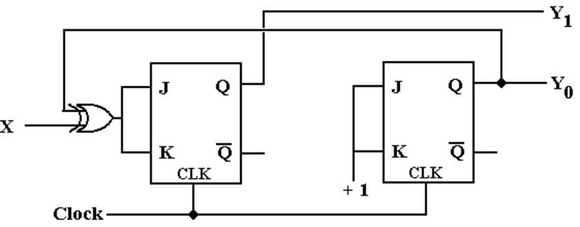
Step 9: Summarize the equations by
writing them in one place.
Here
they are.
J1 = X Å
Y0 K1 = X
Å Y0
J0 = 1 K0 = 1
Step 10:
Draw the Circuit
As
designed, it is:
Step 10:
Draw the Circuit
Implemented
with T Flip–Flops, it is:
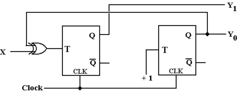
One
could also use a 4–register “one hot” design, with the input X
used to determine the direction of
the shift.