Sample: 4–to–1 MUX and 1–to–4 DEMUX
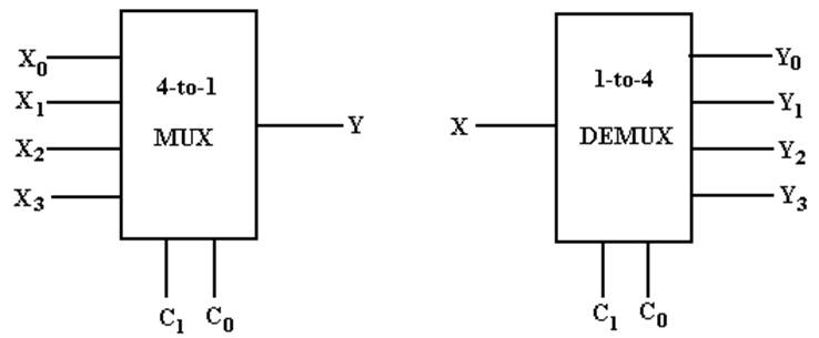
My Notation: X for Input
C for Control
Signals
Y for Output
The Multiplexer Equation
Illustrated for a 4–to–1 MUX
Truth table Denote the multiplexer output by M
|
C1 |
C0 |
M |
|
0 |
0 |
X0 |
|
0 |
1 |
X1 |
|
1 |
0 |
X2 |
|
1 |
1 |
X3 |
Equation Form
![]()
Here is another form of
the equation that is better when X is used as an input.
![]()
Build a 4–to–1 MUX
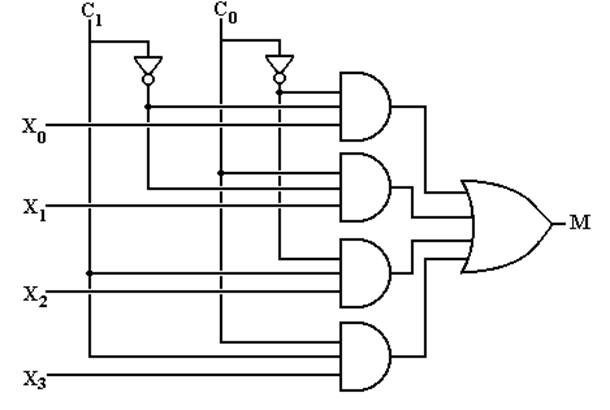
But what about an enable input
for a multiplexer?
What does it mean for the
output of the MUX to be 0?
Multiplexer Attached to a Bus Line
To
control a multiplexer’s connection to a common bus, we use a
tri–state buffer and not an enable input to the MUX. Here I use “E”
as the tri–state control.
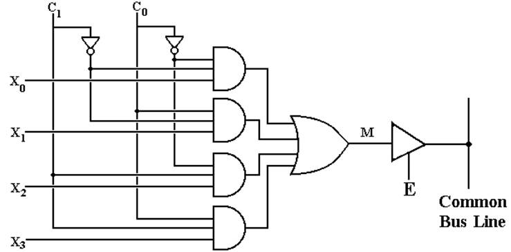
When
E = 1, the selected MUX input is placed on the bus.
When E = 0, the MUX is detached from the bus; another source feeds the bus.
A 1–to–4 DEMUX
|
C1 |
C0 |
Selected Output |
|
0 |
0 |
Y0 = X Other outputs 0 |
|
0 |
1 |
Y1 = X Other outputs 0 |
|
1 |
0 |
Y2 = X Other outputs 0 |
|
1 |
1 |
Y3 = X Other outputs 0 |
Build a 1–to–4 DEMUX
With an Enable
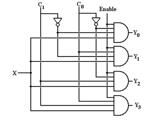
If Enable = 0, all outputs
are 0.
Using A 2N–to–1 MUX
for a Boolean Function of N Boolean Variables
Theorem 1: Any Boolean function of N Boolean variables, N > 0, can be
constructed by a
multiplexer with 2N inputs (usually labeled
IK, IK-1,
… I1, I0) and N control lines, labeled CN-1 …
C0.
Method: Express the Boolean function of N Boolean
variables in Canonical
Sum of Products and
then match the desired function to the
Multiplexer Equation
for a 2N–to–1 MUX.
Example: F2(X, Y, Z) = X·Y
+ X·Z + Y·Z
Step 1: This is a function of three Boolean variables. We must use a
23–to–1
MUX, also called a 8–to–1 MUX.
Using A 2N–to–1 MUX
(page 2)
Step 2: Convert F2(X, Y, Z) = X·Y + X·Z
+ Y·Z to Canonical SOP.
Every product term must have
a literal for each variable.
A literal is either the variable or its complement.
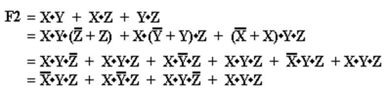
Note that all four terms have
a literal for each of the three variables X, Y, and Z.
Using A 2N–to–1 MUX
(page 3)
Step 3: Convert the function to a form with all 2N
product terms.
Here we convert F2 to have
all eight possible product terms.
Using A 2N–to–1 MUX
(page 4)
Step 4: Write the Multiplexer Equation for an 8–to–1 MUX.
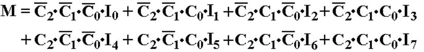
Step
5: Rewrite the equation with C2
= X, C1 = Y, and C0 = Z.
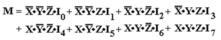
NOTE: Here I use I0, I1, …, I7 as the
MUX inputs because I am using X
to denote one of the Boolean
variables.
Using A 2N–to–1 MUX
(page 5)
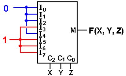
Step 6: Match the two
expressions

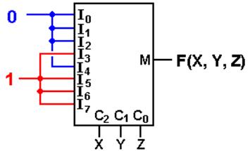
I0 = 0 I1 = 0 I2 = 0 I3
= 1
I4 = 0 I5 = 1 I6 = 1 I7 = 1
with C2 = X, C1
= Y, and C0 = Z.
Using A 2N–to–1 MUX
(Using either a S list or a P list)
For
a S list, connect the listed
inputs to 1 and the others to 0.
For a P
list, connect the listed inputs to 0 and the others to 1.
F(X, Y, Z) = S(3,
5, 6, 7) = P(0, 1, 2, 4)
We
try this with a common circuit emulator, such as Multi–Media Logic,
and find that we need to think a bit more.
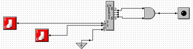
An
Eight–to–One MUX in Multi–Media
Here
is the circuit element selected in the Multi–Media Logic tool.
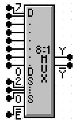
This
is an 8–to–1 MUX with inputs labeled 7 through 0, or
equivalently X7 through X0. This is expected.
The
selector (control) lines are as expected; 2 through 0.
In
my notes, I use M for the output of the Multiplexer. This
figure uses the symbol Y (not a problem) and notes that real
multiplexers also output the complement.
The
only issue here is the enable. Note that
the MUX is
enabled low; this signal must be set to ground in order
for the multiplexer to function as advertised.
Commercial Multiplexer:
Enabled and Not Enabled
At
top, the output is X3. At
bottom, the output is 0.
Carry–Out of
a Full Adder
Here
is a screen shot of my implementation of F(X, Y, Z) = S(3, 5, 6, 7).
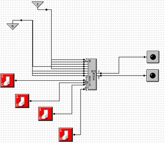
NOTE: Show
simulation here.
Gray Codes:
Minimal Effort Testing
Consider
the above circuit with three basic inputs S2, S1, S0.
How can one test all possible inputs with minimum switching?
One
good answer is to use Gray Codes for input.
Here are the 2–bit and 3–bit codes.
00 000
01 001
11 011
10 010
110
111
101
100
To
generate an (N + 1)–bit code set from an N–bit code set.
1. Write
out the N–bit codes with 0 as a prefix, then
2. Write
out the N–bit codes in reverse with 1 as a prefix.
00,
01, 11, 10 becomes 000, 001,
011, 010, 110, 111, 101, and 100
Testing the
Carry–Out Circuit
If
the Enable switch is set to 1, the output is always 0. Y’ = 1.
Set
the Enable switch to 0 and generate the following sequence.
Start with S2 = 0, S1 = 0, S0
= 0. 0 0 0
Click S0 to get 0 0 1
Click S1 to get 0 1 1
Click S0 to get 0 1 0
Click S2 to get 1 1 0
Click S0 to get 1 1 1
Click S1 to get 1 0 1
Click S0 to get 1 0 0
Where are
the Decoders?
One
will note that the Multi–Media Logic tool does not provide a decoder circuit.
Fortunately,
a 1–to–2N demultiplexer can be made into an N–to–2N
decoder.
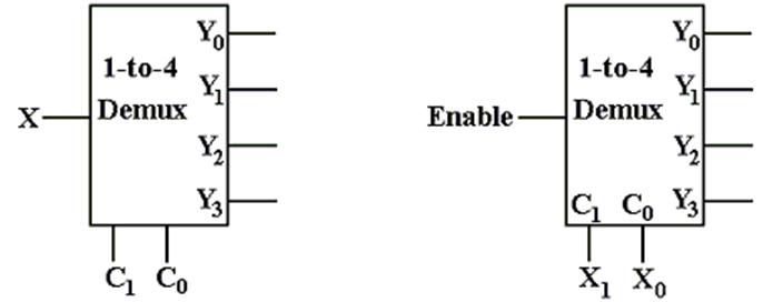
Look
at the circuit to the left. The control
signals C1,C0 select the output to receive
the input X. This is exactly equivalent
to a decoder.
In
the circuit at right, the selected output gets the input, now called “Enable”.
For the demultiplexers we use, the other outputs get a logic 1.
We
can fabricate an active low decoder.
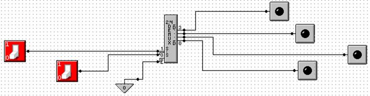
The MUX as
an Active–Low Decoder
Here
is the 2–to–4 Demultiplexer as an 2–to–4 active low decoder.
Here
is an answer to one of the homework problems: use a 2–to–4 decoder for XOR.
The function is either S(1, 2) or P(0, 3).