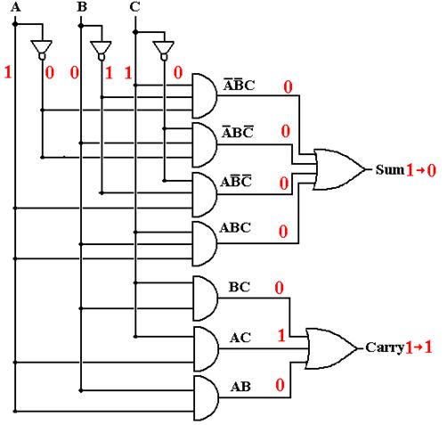
The
Full Adder
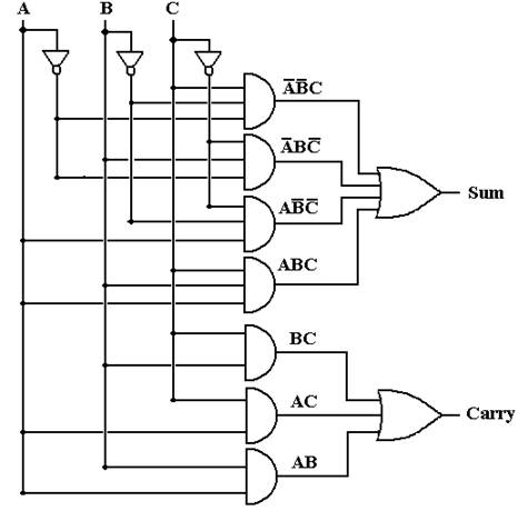
This basic circuit hides the
dynamics associated with changing values.
The
Full Adder
This basic circuit hides the
dynamics associated with changing values.
Gate
Delays
Consider three gates, each of which has input that has
not changed for
some time. The output of each gate
correctly implements its Boolean function.
We now consider what happens as the input to each gate
is changed
suddenly. Note that the output does not
change at the same time as the input.
For a short time, called a “hazard”, the output of the
gate is not that
of the Boolean function supposedly implemented.
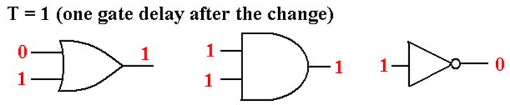
Gate
Delays (More)
For the time duration of one gate delay, the outputs
do not match the inputs.
After one gate delay (about 2
to 10 nanoseconds) the output is correct.
Full
Adder with Gate Delays (Before Input Changes)
Assume the inputs have been
stable for some time.
Full
Adder with Gate Delays (Input Changes at T = 0)
At this point, no outputs are
correct.
Full
Adder with Gate Delays (T = 1)
Some output is correct, but
the upper AND gates are reacting to input at T = 0.
Full
Adder with Gate Delays (T = 2)
The carry out is correct, but
the sum out is reacting to input at T = 1.
Full
Adder with Gate Delays (T = 3)
At T = 3 (and later), all
output is correct.
The
Ripple–Carry Adder
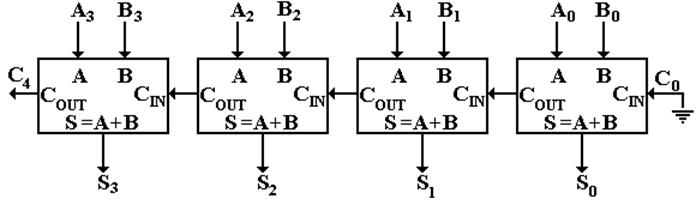
Carry–in to stage K (bit K) is
valid at T = 2·K.
Carry–out from stage K is valid at
T = 2·K + 2.
Sum from stage K is valid at T = 2·K + 3.
32–bit sum valid after stage 31 finishes (65 gate
delays)
This circuit is not used in commercial computers.
Shifters
Logical Shifts
Left Shift Right Shift
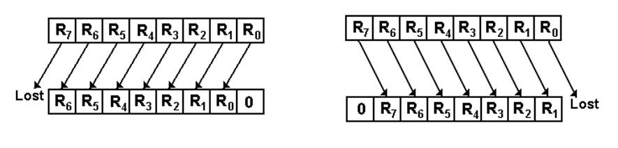
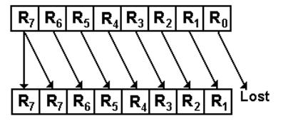
Arithmetic Shifts (Preserve the Sign Bit)
Shifters
(Continued)
Circular Shifts
Left Circular Right
Circular
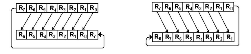
No bits are lost.
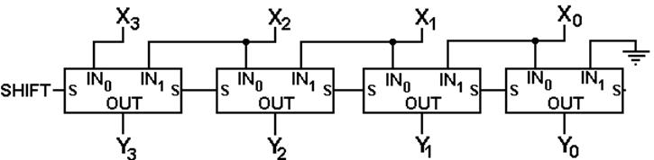
Circuit
for Logical Left Shift
(Only four bits shown)
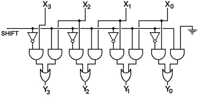
X is the input and Y is the
output
Circuit
for Logical Left Shift
(Simpler Notation)
Two-Stage
Logical Left Shifter
The binary number S1S0
indicates the size of the shift.
Two Stage Left Shifter with
Logical and Circular Shifts
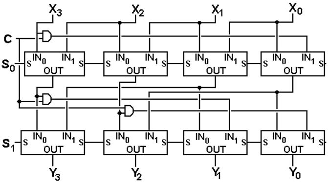
C = 0 for logical shift
C = 1 for circular shift
S1S0 indicates the size of the
shift.
Thirty–Two Bit Shifter
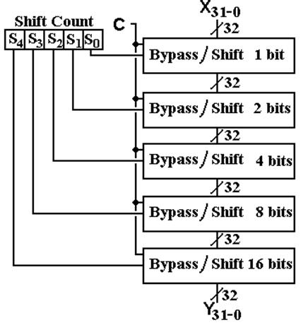
This is a “logarithmic
shifter”. A cross–bar shifter is much
more complex.
Cross–Bar
Shifters
Cross–bar
shifters can perform any number of shifts in one stage.
However, they are much more complex to draw.
Cross–bar
shifters require either tri–state buffers or AND/OR gate
combinations to attach each input to an output.
For
N bits, there are N input lines and N output lines.
Thus
an N–bit cross–bar shifter requires at least N2 gates.
An
N–bit cross–bar shifter may be implemented with N2 tri–state
buffers.
Each
input line may be potentially connected to any one of the N output
lines, thus there are N tri–state buffers for each input line.
If
N = 4, the tri–state count is 16
If
N = 32, the tri–state count is 4,096.
Cross–Bar
Shifters for Circular Shifts
Here
is a four–bit cross–bar shifter for circular left shifts.
Cross–Bar
Shifters for Logical Shifts
Here
is a four–bit cross–bar shifter for circular left shifts.