Encoders and
Decoders:
Details and
Design Issues
Edward L. Bosworth, Ph.D.
TSYS School
of Computer Science
Columbus
State University
Columbus, GA
31907
bosworth_edward@colstate.edu
Review of
Binary Codes
We
now begin a discussion of MSI (Medium
Scale Integration) circuits.
MSI
chips have complete circuits, built from multiple gates, on a single chip.
Two
classes that we study are:
Encoders and Decoders
Multiplexers and Demultiplexers
These devices are based
on binary coded input. We review simple
binary codes.
2–bit codes: 00 0 3–bit codes: 000 0
01 1 001 1
10 2 010 2
11 3 011 3
100 4
101 5
110 6
111 7
Encoders
Encoders
typically have 2N inputs and N outputs.
These
are called 2N–to–N encoders.
Typical
examples include 4–to–2 encoders
(probably not used much)
8–to–3
encoders
16–to–4
encoders
Due
to the prevalence of decimal arithmetic, we also have 10–to–4 encoders.
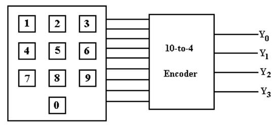
NOTE: We cannot encode 10 items with 3 bits; we need
4 bits to do this.
The Truth Table
for a 10–to–4 Encoder
|
Input |
Y3 |
Y2 |
Y1 |
Y0 |
|
X0 |
0 |
0 |
0 |
0 |
|
X1 |
0 |
0 |
0 |
1 |
|
X2 |
0 |
0 |
1 |
0 |
|
X3 |
0 |
0 |
1 |
1 |
|
X4 |
0 |
1 |
0 |
0 |
|
X5 |
0 |
1 |
0 |
1 |
|
X6 |
0 |
1 |
1 |
0 |
|
X7 |
0 |
1 |
1 |
1 |
|
X8 |
1 |
0 |
0 |
0 |
|
X9 |
1 |
0 |
0 |
1 |
In
the table, we label the inputs X0 through X9, inclusive.
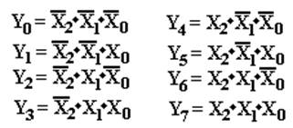
To produce the equations for the outputs, we reason as follows.
Y3
is 1 when either X8 = 1 or X9 = 1.
Y2
is 1 when X4 = 1 or X5 = 1 or X6 = 1 or X7 = 1.
Y1
is 1 when X2 = 1, X3 = 1, X6 = 1, or X7 = 1.
Y0 is 1 when
X1 = 1, X3 = 1, X5 = 1, X7 = 1,
or X9 = 1.
These observations lead to
the following equations, used to design the encoder.
Y3 = X8 + X9
Y2 = X4 + X5 + X6 + X7
Y1
= X2 + X3 + X6 + X7
Y0
= X1 + X3 + X5 + X7 + X9
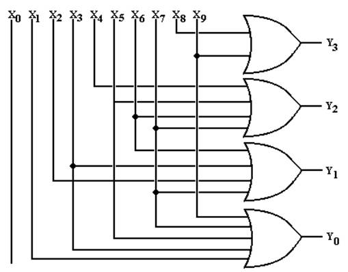
The Circuit
Diagram for the 10–4 Encoder
The equations: Y3 = X8 + X9
Y2 = X4 + X5 + X6 + X7
Y1
= X2 + X3 + X6 + X7
Y0
= X1 + X3 + X5 + X7 + X9
The diagram:
Issues with
Encoders
In
the above encoder, one should note that the input X0 is not
connected
to any output. An output of 0000 always
implies that button 0 is pushed.
Put another way, this circuit
does not distinguish between:
1. No
input button pushed
2. Button
0 pushed.
If
we really needed an indicator that a button had been pushed, we would have
a number of valid options. What we do is
ignore the problem.
Decoders
Decoders
are the opposite of encoders; they are N–to–2N devices.
Typical
examples include 2–to–4 decoders
3–to–8
decoders
4–to–16
decoders
Due
to the prevalence of decimal arithmetic, we also have 4–to–10 decoders.
These
are specialized 4–to–16 decoders with six fewer pins.
N–to–2N
decoders have N inputs, labeled X0,
X1, …., XN–1
2N outputs, similarly labeled Y0, Y1,
etc.
optionally, an enable line.
Decoders
come in two varieties: active high and active low.
We
focus our lectures on active high
decoders:
the selected output goes to
logic 1
the outputs not selected
stay at logic 0.
Description
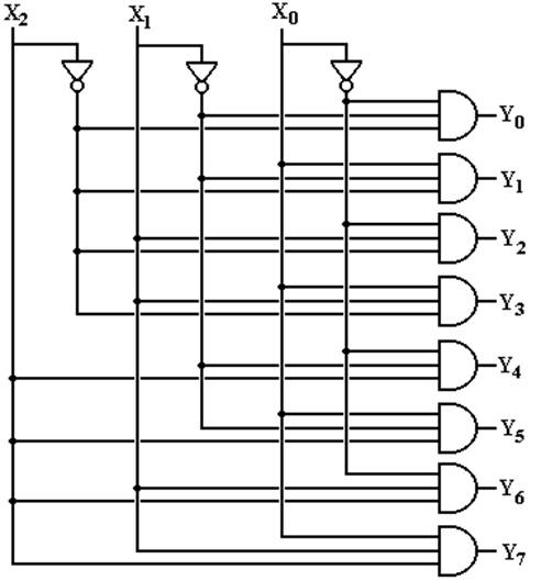
of a 3–to–8 Decoder
This
decoder has three inputs: X2, X1, X0
eight outputs: Y0, Y1, Y2,
Y3, Y4, Y5, Y6, Y7
Its
functioning is best described by a modified truth table.
|
X2 |
X1 |
X0 |
Action |
|
0 |
0 |
0 |
Y0 = 1, all
others are 0 |
|
0 |
0 |
1 |
Y1 = 1, all
others are 0 |
|
0 |
1 |
0 |
Y2 = 1, all
others are 0 |
|
0 |
1 |
1 |
Y3 = 1, all
others are 0 |
|
1 |
0 |
0 |
Y4 = 1, all
others are 0 |
|
1 |
0 |
1 |
Y5 = 1, all others
are 0 |
|
1 |
1 |
0 |
Y6 = 1, all
others are 0 |
|
1 |
1 |
1 |
Y7 = 1, all
others are 0 |
This
gives rise to the equations:
Circuit for
a 3–to–8 Decoder
This
follows from the equations.
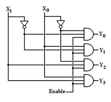
The Enable
Input
Again,
in the above circuit one output will always be active.
Suppose
we want to have a decoder with no outputs active.
This
is the function of the enable input,
often denoted as “E”.
In
an enabled high decoder, when E = 0 no output is active
when E = 1 the
selected output is active
Here is the circuit diagram
for a 2–to–4 decoder with enable input.
Decoders: Circuit Symbols and Truth Tables
We
normally draw a decoder as a box, with inputs to the left and outputs to the
right. Note that the enable is drawn at
the bottom.
The
truth table for an active–high 2–to–4 decoder that is enabled high follows.
|
Enable |
X1 |
X0 |
|
Y0 |
Y1 |
Y2 |
Y3 |
|
0 |
d |
d |
|
0 |
0 |
0 |
0 |
|
1 |
0 |
0 |
|
1 |
0 |
0 |
0 |
|
1 |
0 |
1 |
|
0 |
1 |
0 |
0 |
|
1 |
1 |
0 |
|
0 |
0 |
1 |
0 |
|
1 |
1 |
1 |
|
0 |
0 |
0 |
1 |
The
“d” indicates that when Enable = 0, all outputs are 0 independent of X0,
X1
What Do the
Terms Mean?
Consider
a two–to–four decoder, with two inputs (X1 and X0).
1. Which output becomes active for a given input
pattern?
This is specified by the
definition of a decoder.
2. Does the active output go to logic high or
logic low?
For TTL, this is +5 volts or 0
volts.
3. How to manage the case in which no output should be active?
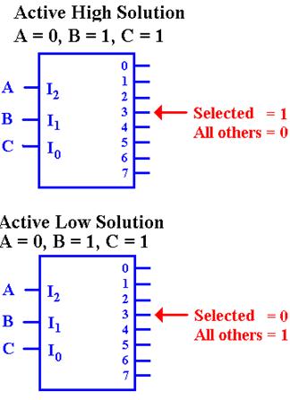
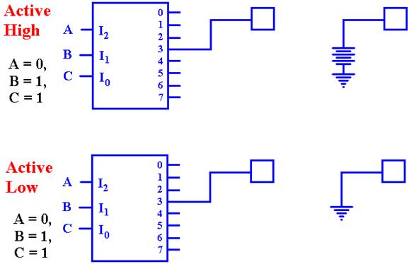
Active High
vs. Active Low
Here are two decoders.
One is active high and one is active low.
In each, output 2 has been selected.
In both circuits, we imagine each of the four outputs
as attached to a LED,
which illuminates when it is fed with a logic 1.
In the circuit at left, only the selected output
illuminates its LED.
It is active high.
In the circuit at right, every output but the selected
output illuminates its LED.
It is active low.
In many circuits, active low appears to be the
preferred mode.
Active–Low,
Enabled–Low Two–to–Four Decoder
Here is a truth table for this circuit.
|
Enable |
X1 |
X0 |
Y0 |
Y1 |
Y2 |
Y3 |
|
1 |
d |
d |
1 |
1 |
1 |
1 |
|
0 |
0 |
0 |
0 |
1 |
1 |
1 |
|
0 |
0 |
1 |
1 |
0 |
1 |
1 |
|
0 |
1 |
0 |
1 |
1 |
0 |
1 |
|
0 |
1 |
1 |
1 |
1 |
1 |
0 |
If
Enable = 1, all outputs are 1.
If Enable = 0, then the input (X1X0)
selects the output that is enabled.
Here are the equations for the circuit. Here the enable is denoted by “E”.
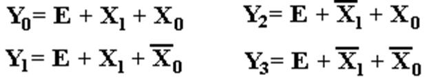
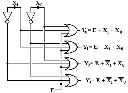
Circuit for
the Enabled–Low, Active–Low
Two–to–Four Decoder
Here it is. “E”
denotes the enable input, but is not properly labeled
as “enable low”. I wanted the circuit
to be a bit simple.
Where are
the Decoders?
One will note that the Multi–Media Logic tool does not
provide a decoder circuit.
Fortunately, a 1–to–2N demultiplexer can be made into an N–to–2N
decoder.
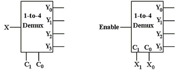
Look at the circuit to the left. The control signals C1,C0
select the output to receive
the input X. This is exactly equivalent
to a decoder.
In
the circuit at right, the selected output gets the input, now called “Enable”.
For the demultiplexers we use, the other outputs get a logic 1.
We
can fabricate an active low decoder.
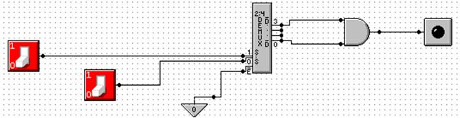
The MUX as
an Active–Low Decoder
Here
is the 2–to–4 Demultiplexer as an 2–to–4 active low
decoder.
Here
is an answer to one of the homework problems: use a 2–to–4 decoder for
XOR.
The function is either S(1, 2) or P(0, 3).
Circuit
Simulation Results
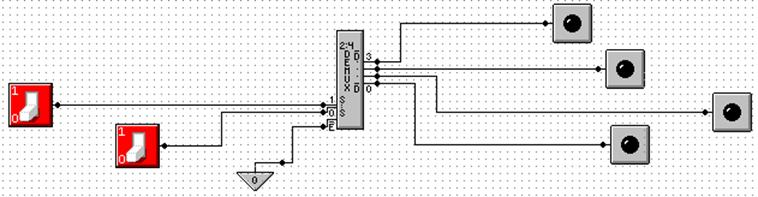
Enabled,
Input 2 Not Enabled
Here we see a composite of two screen shots from
Multimedia Logic.
At left, the decoder is enabled and input 2 is
selected.
The selected output is logic 0.
All other outputs are logic 1.
At right, the decoder is not enabled. All outputs are logic 1.
Design with
an N to 2N Decoder
An
N–to–2N decoder has N inputs, 2N outputs, and some
control lines.
We
can use such a decoder to implement any Boolean expression of N variables.
The
two types of decoders are active high and active low.
Active–high
decoders, connected to OR gates, are used to
implement Boolean expressions in
SOP (Sum of Products) form.
Active–low
decoders, connected to AND gates, are used to
implement Boolean expressions in
POS (Product of Sums) form.
We do not discuss these.
Summary: 2 Boolean variables 2–to–4 decoder
3 Boolean
variables 3–to–8 decoder
4 Boolean variables 4–to–16 decoder
5 Boolean variables 5–to–32 decoder
Implementation
of SOP Expressions with Active High Decoders
These
are the two functions that I have been using for quite some time.
With
the decoder approach, it is best to design from the S–list expression.
If
one has a truth table or canonical SOP expression, it is easier to first
convert to the
S–list and then proceed
with the design.
Here
are F1 and F2. F1 = S(1, 2, 4, 7) and F2 = S(3, 5, 6, 7)
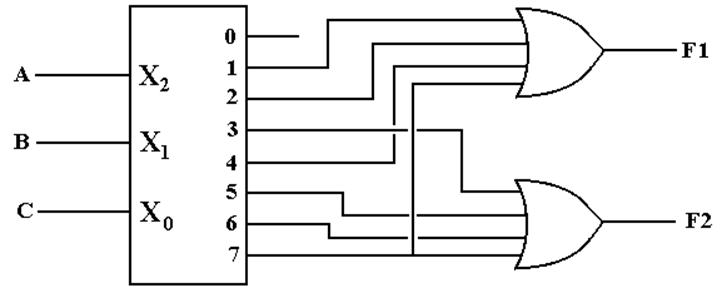
Just connect the numbered
outputs into an OR gate and get the function.
Active Low
Decoders
First,
let’s use 3–to–8 decoders to describe the difference between
active high and active low.
In
the active–high decoder, the active output
is set to +5 volts (logic 1), while the other
outputs are set to 0 volts (logic 0).
In
the active–low decoder, the active output
is set to 0 volts (logic 0), while the other
outputs are set to +5 volts (logic 1).
Enabled Low,
Active Low Decoders
All
commercial decoders have an enable input; most are enabled low.
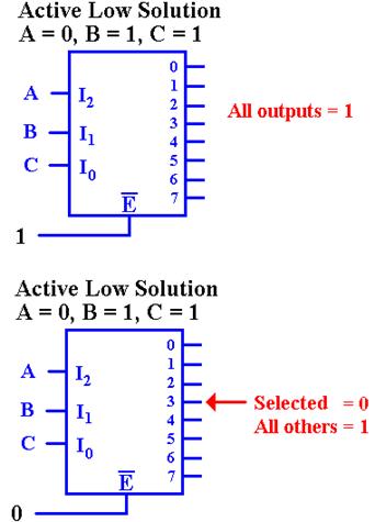
Since
the decoder is enabled low, when the input
signal E’ = 1, none of the decoder outputs are active.
Since the decoder is active low, this means that all of
the outputs are set to logic 1 (+5 volts).
Since
the decoder is enabled low, when the input signal E’ = 0,
the decoder is enabled and the selected output is active. Since
the decoder is active low, this means that the selected output is
set to logic 0, and all other outputs are set to logic 1.
Why Active
Low / Enabled Low?
This
is a conjecture, but it makes sense to me.
The
active–high decoder is providing power to the device it enables.
The
active–low decoder is just providing a path to ground for the device it
enables.
It is likely that this approach yields a faster circuit.
Back To
Active High: A Look At F2
Seeking
a gate that outputs 1 if at least one of its inputs is 1, we are led to the OR
gate.
Active Low:
F2(X, Y, Z) = P(0, 1, 2, 4)
F2
is 1 if and only if none of the outputs Y0, Y1, Y2,
or Y4 are selected.
Specifically, each of
those outputs must be a logic 1. This
leads to an AND gate implementation.