What Do the Terms Mean?
Consider
a two–to–four decoder, with two inputs (X1 and X0).
1. Which output becomes active for a given input
pattern?
This is specified by the
definition of a decoder.
2. Does the active output go to logic high or
logic low?
For TTL, this is +5 volts or 0
volts.
3. How to manage the case in which no output should be active?
Consider a Simple Implementation
This circuit implements a very simple active–high
two–to–four decoder.
The active output goes to logic 1 and the other three
stay at logic 0.
However, exactly one output is active at any time.
Disabling All Outputs
The goal is to have a circuit when at most one output is active at
any time.
We want to have the option of having no outputs
active.
This is the reason for the enable input.
Here we have the option of making all outputs to be inactive.
Active–High, Enabled–High Two–to–Four
Decoder
Here is a truth table for this circuit.
|
Enable |
X1 |
X0 |
Y0 |
Y1 |
Y2 |
Y3 |
|
0 |
d |
d |
0 |
0 |
0 |
0 |
|
1 |
0 |
0 |
1 |
0 |
0 |
0 |
|
1 |
0 |
1 |
0 |
1 |
0 |
0 |
|
1 |
1 |
0 |
0 |
0 |
1 |
0 |
|
1 |
1 |
1 |
0 |
0 |
0 |
1 |
If
Enable = 0, all outputs are 0.
If Enable = 1, then the input (X1X0)
selects the output that is enabled.
The ability to “turn off” all outputs from a circuit
element, such as a
decoder, allows for greater flexibility in circuit design.
However, few MSI circuit elements are either enabled
high or active high.
Active High vs. Active Low
Here are two decoders.
One is active high and one is active low.
In each, output 2 has been selected.
In both circuits, we imagine each of the four outputs
as attached to a LED,
which illuminates when it is fed with a logic 1.
In the circuit at left, only the selected output
illuminates its LED.
It is active high.
In the circuit at right, every output but the selected
output illuminates its LED.
It is active low.
In many circuits, active low appears to be the
preferred mode.
Active–Low, Enabled–Low Two–to–Four
Decoder
Here is a truth table for this circuit.
|
Enable |
X1 |
X0 |
Y0 |
Y1 |
Y2 |
Y3 |
|
1 |
d |
d |
1 |
1 |
1 |
1 |
|
0 |
0 |
0 |
0 |
1 |
1 |
1 |
|
0 |
0 |
1 |
1 |
0 |
1 |
1 |
|
0 |
1 |
0 |
1 |
1 |
0 |
1 |
|
0 |
1 |
1 |
1 |
1 |
1 |
0 |
If
Enable = 1, all outputs are 1.
If Enable = 0, then the input (X1X0)
selects the output that is enabled.
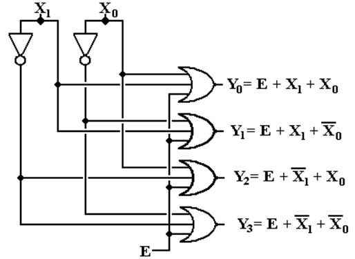
Here are the equations for the circuit. Here the enable is denoted by “E”.
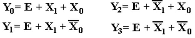
Circuit for the Enabled–Low, Active–Low
Two–to–Four Decoder
Here it is. “E”
denotes the enable input, but is not properly labeled
as “enable low”. I wanted the circuit
to be a bit simple.
Circuit Simulation Results
Enabled,
Input 2 Not Enabled
Here we see a composite of two screen shots from
Multimedia Logic.
At left, the decoder is enabled and input 2 is
selected.
The selected output is logic 0.
All other outputs are logic 1.
At right, the decoder is not enabled. All outputs are logic 1.
Commercial Multiplexer: Enabled and Not
Enabled
At top, the output is X3. At bottom, the output is 0.