You can
store a sequentially organized file on any type of device and for any type of
file, such as master, transaction,
and archival. Such a file can even be
stored on punch cards, such as the 80–column punch cards that were once used
to store programs and data. While punch cards have not been much used to
store data since about 1990 (due to the
storage space required), a data set on punched cards may be considered as being
in unblocked form (see below)
on a magnetic tape (also little used since about 2000).
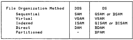
Indexed Sequential (ISAM) File Organization
Indexed
sequential organization for master files lets one access records in ascending
sequence and also support indices
that enable access of any record randomly by key. The ISAM organization is very efficient, but
not flexible when
records are inserted and deleted at random.
The newer VSAM method is more flexible and provides equivalent
services; for this reason we mention ISAM only as an item of historical
interest.
Direct File Organization
Direct file
organization facilitates direct access for any record in a master file. The main advantage is that this
method provides fast access for records and is thus particularly useful for
online systems.
Virtual Storage Access Method (VSAM)
Virtual
storage access method (VSAM) supports three organization types. Entry–sequenced is equivalent to sequential
organization, key–sequenced is equivalent to ISAM, and relative–record is
equivalent to direct. Disk storage
devices,
but not tape, support indexed sequential, VSAM, and direct organization. Chapters 26, 27,
and 28 cover sequential, ISAM, and VSAM, respectively.
ACCESS METHODS
An access
method is the means by which the system performs input/output requests. The methods depend on the
file organizations and the file type of accessing required.DOS supports four
methods and OS supports seven.
The latest implementation of z/OS, which is the Operating System for the z/10
and z/11, probably support more.
Processing of External Storage Devices
Major
similarities between tape and disk are that records may be of virtually any
length, of fixed or variable length, and
clustered together into one or more records per block. It should be mentioned that disk records are
not partitioned into
fixed length sectors, as is the case for computers running MS–DOS or its
equivalent, MS–Windows. When we discuss
the logical disk architecture as implemented by modern IBM Mainframe
(Enterprise Server) computers, we shall have
occasion to mention again this logical record architecture.
There are,
however, two major differences in processing tape and disk. First, each time you read or write, the tape
drive
starts, transfers the data, and then stops, whereas a disk drive rotates
continuously. The sole exception to this
is the now
obsolete external “floppy disk” in which the disk rotation is discontinued
after a period of inactivity in order to avoid
wear on the motor. The second difference
is that update of records on tape involves rewriting of the entire changed file
on another reel of tape. Disk records
can be updated in place, but the mechanical problems of tape movement mean
that in–place replacement of records is likely to be error prone and should be
avoided.
Identification of External Devices
Both disk and tape have unique ways of identifying their
contents to help in locating files and in protecting them
from accidental erasure.
Tape file identification. At the beginning of the
tape reel is a volume label, which is a record that identifies the reel
being used. Immediately preceding each file on the tape is a header label, which
describes the file that follows. This
record contains the name of the file (for example, INVENTORY FILE) and the date
the file was created.
Following the header label are the records that comprise the data file.
The last record following the file is a trailer label, which is
similar to the header label but also contains the number
of blocks written on the reel. The operating system automatically handles the
header and trailer labels.
Disk file identification. To keep track of all the
files it contains, a disk device uses a special directory (volume table of contents,
VTOC) at the beginning of its storage area. The directory includes the names of
the files, their locations on disk,
and their present status.
Packed
and Binary Data
Tape and
disk records can contain numeric fields defined as zoned, binary, or packed.
Packed format involves two
digits per byte plus a half-byte for the sign, such as
PAYMENT
DS PL4
In this case, the field length is 4 bytes, stored as dd | dd | dd | ds, where d is a digit and s is
the sign.
If the field is defined as binary, watch out for erroneous alignment of the
field when you read it into
main storage. The following binary fields are both 4 bytes long:
Aligned on a fulIword boundary: PAYMENT1 DS F
Not aligned on a boundary: PAYMENT2 DS FLA
The assembler automatically aligns PAYMENT1 on a
fullword boundary, whereas the assembler defines
PAYMENT2
at its proper (unaligned) location.
Unblocked
and Blocked Records
Disk and tape devices recognize blocks of data, which consist of one or more records.
A blank space, known as
an interblock
gap (IBG), separates one block from another. The length of an IBG on
tape is 0.3 to 0.6 inches
depending on the device, and the length of an IBG on disk varies by device and
by track location. The IBG
has two purposes: (I) to define the start and end of each block of data and (2) to provide space for the tape
when the drive stops and restarts for each read or write of a block.
Records that are stored one to a block are called unblocked. As shown in Fig. 25-1(a), following each block is an IBG.
To reduce the amount of tape and disk storage and to speed
up input/output, you may specify a blocking
factor,
such as three records per block, as shown in Fig. 25-1(b). In this format, the
system writes an entire block of three
records from main storage onto the device. Subsequently, when the system reads
the file,it reads the entire block of
three records from the device into storage. All programs that subsequently read
the file must specify the same record
length and block length. Blocking
records makes better use of disk and tape storage but requires a larger buffer
area in main storage to hold the block.
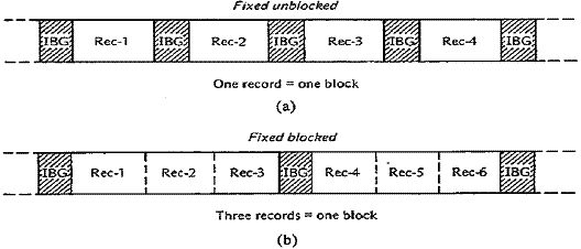
Figure
25–1 (a) Unblocked records. (b) Blocked records
Input Buffers
The action of an input operation depends on whether
records are unblocked or blocked. If unblocked, the operation transfers
one record (block) at a time from the device into the input/output buffer in
your program. The following example of
blocked
records assumes three records per block.
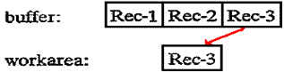
Initially, the input operation transfers the first block from the device
into the buffer
(I/O area) in your program and delivers the first record to your program's work
area:
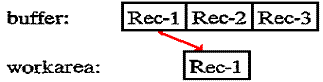
For the
second input executed, the operation does not have to access the device. Instead, it simply delivers the second
record from the buffer into your program’s work area:
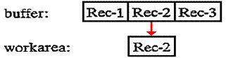
And for the third input executed, the operation delivers the third record from the buffer to your program’s work area:
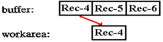
While the
program processes the third record in the work area, the system can read ahead
and transfer the second
block (containing records 4, 5, and 6) from the device into the buffer in your
program. For the fourth input executed,
the operation delivers the first record from the buffer into your program’s
work area:
Output
Buffers
The action of an output operation depends on whether
records are unblocked or blocked. If unblocked, the output
operation transfers one record (block) at a time from your work area to the
buffer in your program and then to the
output device. The following example of
blocked records assumes three records per block. The first output operation
writes the record in the work area to the first record location in the output
buffer, but not to the output device:
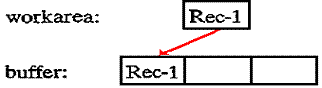
No actual
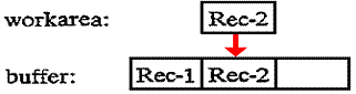
physical writing to the output device occurs at this time. The second output operation writes the
record in the work area to the second record location in the buffer:
Similarly, the
third output operation writes its record from the work area to the third record
location in the buffer.
Now the buffer is full, the system can physically write the contents of the
buffer, this block of three records,
to the external device.
The CLOSE
operation automatically writes the last block of data to the output
device. This last block may validly
contain fewer records than the blocking factor specifies; consider a program
that writes ten records with a blocking
factor of three. When the CLOSE
operation is called, the buffer will contain one valid record (record 10)
and two empty slots.
NOTE ADDED BY Ed Bosworth
There is some security advantage to having each physical
write, including the last CLOSE, completely clear the
buffer before any additional logical writes take place.
Fixed-Length
and Variable-Length Records
Records
and blocks may be fixed in length, where each has the same length throughout
the entire file, or variable in
length, where the length of each record and the
blocking factor are not predetermined.
There are five formats:
1. Fixed, unblocked: one record of fixed length per block
2. Fixed, blocked: more than one fixed-length record per block
3. Variable, unblocked: one variable-length record per block
4. Variable, blocked: more than one variable-length record per block
5. Undefined: contents of no defined format
(Not
all systems support this format.)
MAGNETIC
TAPE STORAGE
The magnetic tape used in a computer system is similar to
the tape used by conventional audiotape recorders; both use
a similar coating of metallic oxide on flexible plastic, and both can be
recorded and erased. Its large capacity and its
reusability make tape an economical storage medium.
Data records on tape are usually, but not necessarily,
stored sequentially, and a program that processes the records
stints with the first record and reads or writes each record consecutively.
The main users of tape are installations such as
department stores and utilities that require large files that they process
sequentially. Many installations use disk for most general processing and use
tape for backing up the contents of the
disk master files at the end of each workday. Consequently, if it is necessary
to rerun a job because of errors or
damage, backup tapes are always available.
Characteristics
of Tape
The most common width of a reel of magnetic tape is 1/2
inch, and its length ranges from 200 feet to the common
2,400 feet, with lengths as long as 3,600 feet. A tape drive records data as
magnetic bits on the oxide side of the tape.
Storage format. Data is stored on tape according to
tracks. The tape in Fig. 25–3 shows the arrangement of a nine–track
tape; it has nine horizontal tracks, each of which represents a particular bit
position. Each vertical set of 9 bits constitutes
a byte, of which 8 bits are for data and 1 bit is for parity. In the 1950’s and
1960’s, the seven–track format was also
popular, having six bits for data and 1 bit for parity. By the mid–1970’s, this format was becoming
unpopular,
and seven–track tape readers were hard to find.
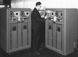 The picture at left (Fig.
25–2) shows the first magnetic tape drive produced
The picture at left (Fig.
25–2) shows the first magnetic tape drive produced
by IBM. This was the IBM 729, a 7–track
device, first released in 1952.
The novelty of the design is reflected by an actual incident at the IBM
receiving dock. The designers were
expecting a shipment of magnetic
tape when they were called by the foreman of the dock with the news that
“We just received a shipment of tape from 3M, but are going to
send it back … It does not have any glue on it”
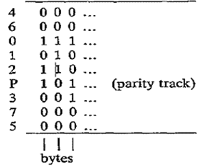
Figure 25–3
Data on Tape, with Bytes in Vertical Stripes
As you can
see, the tracks for each of the bits are not in the expected sequence. The tracks for bits 4 and 5,
the least used, are in the outer area where the tape is more easily
damaged. The first byte, on the left,
would appear in main storage as follows:
|
Bit Number |
0 |
1 |
2 |
3 |
4 |
5 |
6 |
7 |
P |
|
Bit Value |
1 |
0 |
1 |
0 |
0 |
0 |
0 |
0 |
1 |
The data value stored in the byte is
“1010 0000” or hexadecimal “A0”. The
parity bit is set for odd parity, in which
each byte will be represented with an odd number of 1 bits in its vertical
stripe. Here, the data byte contains an
even number of 1 bits, so P is set to 1.
Storage density. Tape density is measured by the
number of stored characters, or bytes,
per inch (bpi), such as 800,
1,600, or 6,250 bpi. Therefore, a 2,400-foot reel with a recording density of
1,600 bpi could contain 46 million bytes,
which is equal to over a half-million 80-byte records. Double-density tape stores data on 18 tracks,
representing
2 bytes for each set of 18 vertical bits.
This however is an unusual format.
Tape speed. Tape read/write speeds vary from 36 to 200
or more inches per second. Thus a tape drive that reads
1,600 bpi records at 200 inches per second would be capable of reading 320,000
bytes per second.
Other high-speed cartridge drives transfer data at up to 3 million bytes
per second.
Tape markers. A reflective strip, called a load
point marker, located about 15 feet from the beginning of a tape reel,
indicates where the system may begin reading and writing data. Another
reflective strip, an end-of-tape marker,
located about 14 feet from the end of the reel, warns the system that the end
of the reel is near and that the system
should finish writing data. Both the load point marker and the end-of-tape
marker are on the side
of the tape opposite the recording oxide.
Tape
File Organization
A file or data set on magnetic tape is typically stored in
sequence by control field or key, such as inventory number.
For compatibility with disks, a reel of tape is know as a volume. The simplest case is a one-volume file, in
which
one file is entirely and exclusively stored on one reel (volume).
An extremely large file, known as a multivolume file, requires more than one reel. Many
small files may be stored
on a multifile volume, one
after the other. The primary problem
here is that you may have to rewrite
the entire reel just to update one of the files.
Unblocked
and Blocked Tape Records
As an example of the effect of blocking records on tape,
consider a file of 1,000 records each 800 bytes long. Tape density
is 1,600 bytes per inch, and each IBG is 0.6 inches. How much space does the
file require given (a) unblocked records and
(b) a blocking factor of 5? Calculate the size of a record of 800 bytes as 800
/ 1,600 = 0.5 inches.
(a) Unblocked records
One block = one record = 800 bytes
Length
of one block = 800 bytes/1,600 bpi =
0.5”
Length of one mG = 0.6”
Space required for one block = 1.1"
Space required for file = 1,000 blocks x 1.1" = 1,100"
(b) Blocked records
One block = five records = 4;000 bytes
Length
of one block = 4,000 bytes/1,600 bpi =
2.5"
Length of one IBG = 0.6”
Space required for one block = 3.1"
Space required for file = 200 blocks x 3.1" = 620"
As can be seen, the blocked records require considerably less space because there are fewer Interblock Gaps.
Standard
Labels
Under the various operating systems, tape reels require
unique identification. Each reel, and each file on a reel, usually
contains descriptive standard labels supported by the operating systems (1) to
uniquely identify the reel and the file for
each program that processes it and (2) to provide compatibility with other IBM
systems and (to some degree)
with systems of other manufacturers.
Installations typically use standard labels. Nonstandard
labels and unlabeled tapes are permitted but are not covered in
this text. The two types of standard labels are volume and file labels. Figure
25–4 illustrates standard labels for one file
on a volume, a multivolume file, and a multifile volume. In the figure, striped
lines indicate IBGs, and TM (for tape mark)
is a special marker that the system writes to indicate the end of a file or the
end of the reel.
Volume
Labels
The volume label is the first record after the load point
marker and describes the volume (reel). The first 3 bytes
contain the identification VOL. Although some systems support more than one
volume label, this text describes
only the common situation of one label.
On receipt of a new tape reel, an operator uses an IBM
utility program to write a volume label with a serial number
and a temporary header file label. When subsequently processing the reel, the
system expects the volume label to be
the first record. it checks the tape
serial number against the number supplied by the job control command, TLBL
under DOS or DD under OS.
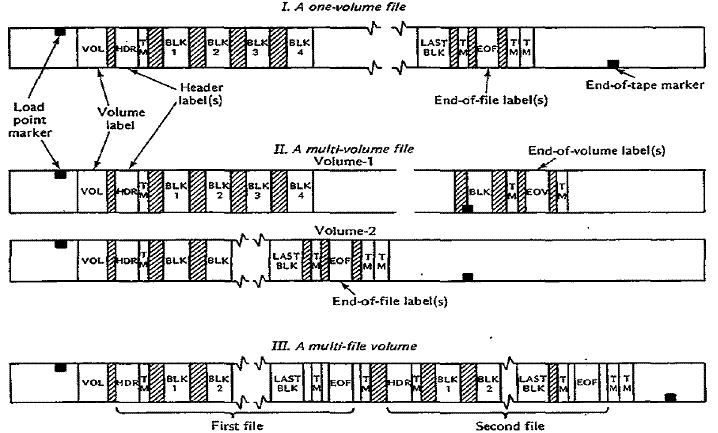
Figure 25–4 Magnetic Tape Standard Labels
The following describes each field in the 80–byte
standard volume label:
|
Positions |
Name |
Description |
|
01 – 03 |
Label identifier |
Contains
the three characters “VOL” to |
|
04 |
Volume label number |
Some systems permit more than one volume label; this field contains their numeric sequence. |
|
05 – 10 |
Volume serial number |
The permanent unique number assigned when the reel is received. This number also becomes the file serial number in the header label. |
|
11 |
Volume security code |
A special security code supported by the OS |
|
12 – 41 |
Unused |
Reserved for use by IBM. |
|
42 – 51 |
Owner’s identification |
May be used under OS to identify the owner’s name and address. |
|
52 – 80 |
Unused |
Reserved/ |
File Labels
A tape volume contains a file of data, part of a file, or
more tban one file. Each file has a unique identification to
ensure, for example, that the system is processing the correct file and that
the tape being used to write on is validly
obsolete [presumably meaning that its contents can be
overwritten – ELB]. Two file labels for each file,
a header label and a trailer label, provide this identification.
The following describes each field in the standard file
label for both header and trailer labels.
(This table, accurate for the late 1970’s, must now be
obsolete; note the two digit “yy”
format
for the year number in the Creation Date and Expiration Date fields. – ELB)
|
Position |
Name |
Description |
|
01 – 03 |
Label |
HDR if a header label, EOF if
the end of a file, |
|
04 |
File label |
Specifies the sequence of file
labels for systems that support more than one. OS supports 2 labels each for |
|
05 – 21 |
File identifier |
A unique name that identifies the file. |
|
22 – 27 |
File serial |
The same identification as the volume serial number for the first or only volume of the file. |
|
28 – 31 |
Volume sequence number |
Sequence of volume numbers for multivolume files. The first volume for a file contains 0001, the second 0002, etc. |
|
32 – 35 |
File sequence number |
The sequence of file numbers for multifile volumes. The first file in a volume contains 0001, the second 0002, etc. |
|
36 – 39 |
Generation |
Each time the system rewrites a file, it increments this number by 1 to identify the edition of the file. |
|
40 – 41 |
Version number |
Specifies the version of the
generation number of the file. |
|
42 – 47 |
Creation Date |
The year and day when the
file was written. Format is |
|
48 – 53 |
Expiration Date |
The year and day when the
file may be overwritten. |
|
54 |
File security code |
A special security code used by OS. |
|
55 – 60 |
Block count |
Used in trailer labels for
the number of blocks since |
|
61 – 73 |
System code |
An identification for the operating system. |
|
74 – 80 |
Unused |
Reserved, but probably now used to expand the year numbers for Creation & Expiration date. Corrections for the Y2K problem cannot invalidate older file formats. |
Header
label. A header label precedes each file. If the file requires more than
one reel,
each reel contains a header label, numbered from 001. If a reel contains more
than
one file, a header label precedes each file.
The header label contains HDR in the first 3 bytes; the
file identification (such as CUSTOMER RECORDS),
the date the file may be deleted, and so forth.
The system expects a header label to follow the volume label
immediately and checks the file identification, date, and other details against
information supplied by job control.
OS supports two header labels, HDRI and HDR2, with the
second label, also 80 bytes, immediately following
the first. Its contents include the record format (fixed, variable, or undefined),
block length, record length,
and density of writing on the tape.
Trailer label. A trailer label is the last record
of every file. (OS supports two trailer labels.) The first 3 bytes contain
EOV if the file requires more than one reel and the trailer label is the end of
a reel but not end of the file.
The first 3 bytes contain EOF if the trailer label is the end of the file.
The trai1er
label is otherwise identical to the header label except for a block count
field. The system counts the
blocks as it writes them and stores the total in the trailer label.
Subsequently, when reading the reel, the system
counts the blocks and checks its count against the number stored in the trailer
label.
IOCS
FOR MAGNETIC TAPE
The system (IOCS for DOS and Data Management for OS)
performs the following
functions for input and for output.
Reading
a Tape File
The processing for reading a tape file is as follows:
1. Processing
the Volume Label. On OPEN, IOCS reads the volume label and
compares its serial number to that on the TLBL or DD job control entry.
2. Processing
the Header Label. IOCS next reads the header label and checks that
the file identification agrees with that on the job control entry to ensure
that it is
reading the correct file. For a multivolume file, the volume sequence numbers
are normally in consecutive, ascending. sequence.
3. Reading
Records. The GET macro reads records, specifying either a work area or
IOREG. If the tape records are
unblocked, each GET reads one record (a block) from tape into storage. If
records are blocked, IOCS performs
the required deblocking.
4. End-of-Volume.
If IOCS encounters the end-of-volume label before the end–of–file (meaning
that the file
continues on another reel), IOCS checks that the block count is correct. It
rewinds the reel, opens a reel on an
alternate tape drive, checks the labels, and resumes reading this new reel.
5. End-of-File.
Each GET operation causes IOCS to transfer a record to the work area. Once
every record has
been transferred and processed and you attempt to perform another GET, IOCS
recognizes an end-of-file condition.
It then checks the block count, (usually) rewinds the reel, and transfers
control to your end-of-file address designated
in the DTFMT or DCB macro. You should now CLOSE the tape file. To attempt
further reading of a
rewound tape file, you must perform another OPEN.
Writing
a Tape File
The processing for writing a tape file is as follows:
1. Processing
the Volume Label. On OPEN, IOCS checks the volume label (VOL)
and compares its serial number
to the serial number (if any) on the job control entry.
2. Processing
the Header Label. IOCS next checks the header label for the expiration
date. If this date has passed,
IOCS backspaces the tape and writes a new header (HDR) over the old one, based
on data in job control. If this is a
multivolume file, IOCS records the volume sequence number for the volume. It
then writes a tape mark.
3. Writing
Records. If the tape records are unblocked, each PUT writes one record
(a block) from tape into storage.
If records are blocked, IOCS performs the required blocking.
4. End-of-Volume.
If10CS detects the end-of-tape marker near the end of the reel, it writes
an EOV trailer label,
which includes a count of all blocks written, followed by a tape mark. Since
the reflective marker is on the opposite
side of the tape, data may be recorded through its area. If an alternate tape
drive is assigned, IOCS opens the
alternate volume, processes its labels, and resumes writing this new reel.
5. End-of-File.
When a program closes the tape file, 10CS writes the last block of data, if
any. The last block may
contain fewer records than the blocking factor specifies. IOCS then writes a
tape mark and an EOF trailer label
with a block count. Finally, IOCS writes two tape marks and deactivates the
file from further processing.
DISK STORAGE
A direct access storage device (DASD),
which includes magnetic disk storage and the less common drum storage,
is a device that can access any record on a file directly. Diskettes, a common
and familiar storage medium on micro-
and minicomputers, store data in a similar manner. This section describes the
details of the larger magnetic disk devices
used in data processing installations. (ELB: Basically, a DASD is any device that can be addressed and
used as if it
were a disk.
Today, this might include USB Drives, which are formatted as disks in
order to facilitate their portability
among computer systems. A CD–ROM, though called a disk, is formatted
and accessed more like a magnetic tape;
it is not a
DASD.
Historically, the first DASD
built was a magnetic drum memory, which was invented in 1932 for use in early
calculating
machines. A
drum is a large metal cylinder that is coated on the outside surface with a ferromagnetic
recording material.
This surface is divided into parallel tracks, each of
which would resemble a circle, or line that encircles the cylinder.
A row or read–write heads runs along the axis of the
drum, one for each track.
The figure below shows magnetic
drums from two commercial firms, IBM and UNIVAC. The magnetic drum on the left
is one for the IBM 650, from about 1954. This drum was four inches in diameter, 16
inches long, and stored 2,000 10–digit
numbers (possibly 20 KB). The drum rotated at 12,500 rpm. The drums on the right are probably variants
of the Model 1124,
made by UNIVAC beginning in about 1953. These would store between 18 KB and 36 KB on
133 to 270 parallel tracks.
The picture on the right probably dates to 1958.
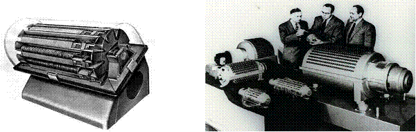
Figure 25–5
Magnetic Drum Memories
The “golden era” of magnetic drum
memories seems to have begun in the early 1950’s, when they replaced the
smaller
and much more fragile Williams–Kilburn tubes, to the
middle of the 1960’s, when magnetic disk technology as we know
it became more cost effective. The technology persisted because it was
useful; as late as 1980, PDP–11/45 computers
that used drums for swapping (management of virtual
memory) were still in use.
The first commercial disk drive
seems to have been the IBM 350, an integral part of the IBM RAMAC 305 System
(Random Access Method for Accounting and Control)
introduced in 1956. The figure below
shows two views, one
showing the mechanism of the disk drive itself and one showing the IBM 350 as a part
of the RAMAC 305. The RAMAC
disk had fifty aluminum disks, each twenty–four inches
in diameter. Its total storage capacity
was variously quoted at
either 4.4 MB or five million characters. The disks spun at 1200 rpm, yielding an
average latency of 1/20 second), and
transferred data at 8,800 characters per second. According to IBM, the disk would store the
equivalent of 64,000
punched cards.
The standard punched card of the time was the IBM 5081, which was
usually 0.007 inches thick.
Thus the system would store about the same amount of
data as 37 feet of cards, as
64,000 · 0.007 = 64,000 · 7/1000 = 64 · 7 = 448 inches = 37 feet, 4 inches.
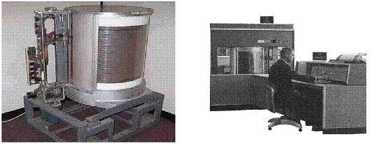
Figure 25–6 Two Views of the IBM RAMAC: IBM 305 and IBM
350
Each disk storage device contains
a number of thin circular plates (or disks) stacked one on top of the other.
Both sides
of each plate (except the outer top and bottom on some
devices) have a coat of ferrous oxide material to permit recording.
(ELB: Before the introduction of the IBM “
drives. This
resulted in possible damage to the outer top and outer bottom recording
surface, which were not used in order
to avoid data corruption. A disk pack with six platters, as shown in
the figure below, would have either ten
or twelve recording surfaces.
I have decided to include more on
the history of this disk drive. This was
officially named the IBM 3340 Direct Access
Storage Facility, but unofficially named “
modules; the name was selected after the famous
stuck. The
significance of this technology was it was the first to package the disk packs,
read heads, and read arm
assembly in a sealed unit that could be removed as a
single module. With reduced possibility
of contamination of
the recording surfaces of the disk, it became possible
to increase recording densities and use all of the available surfaces.
The IBM 3340 was introduced in March 1973 for use with
the IBM System/370.)
As Fig. 25–7 shows, each disk contains circular tracks for
storing data records as magnetized bits. Each track contains
the same number of bits (and bytes) because the bits are spaced more closely
together on the innermost tracks. (ELB:
Modern designs partition the surface into a number of
zones. Within each zone, each track
contains the same number
of bytes, but tracks in an outer zone contain more bytes
than those in an inner zone.)
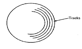
Figure 25–7 Disk Surface and Tracks
The disks are constantly rotating on a vertical shaft. As
Fig. 25–8 shows, the disk device has a set of access arms that
move read/write heads from track to track. The heads read data blocks from a
disk track into main storage and write
data blocks from main storage onto a disk track. Because the disks spin
continually, the system has to wait for a required
data block to reach the read/write heads.
(ELB:
Note that this configuration does not use the top surface of the top
platter or the bottom surface of the bottom platter;
it has six platters and ten recording surfaces.
A
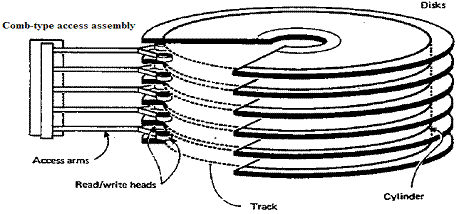
Figure 25–8 Disk
read/write mechanism (Non
Disk storage devices permit processing of records both
sequentially and randomly (directly). As a result, programs can
read unsorted records from a transaction file and use them to randomly update
matching master records on disk. Disk
storage therefore facilitates online processing where users can at any time
make inquiries into a file and can enter
transactions for updating as they occur.
(ELB: There are two factors of
importance when considering a disk: maximum transfer rate and disk access
times.
The maximum transfer rate is computed simply: it is
the number of bytes on a disk track divided by the time to read
the entire track.
Consider a disk rotating at 15,000 rpm, or one revolution every 1/250 =
0.004 second.
If the track holds 4 MB of data, the transfer rate is
4MB /0.004 second = 1 GB/second.
Times of importance when
assessing disk speed, the average
latency and the track access time, commonly
called
“seek time”. The latency is computed
as the time for the disk to spin one half of a turn; if the read/write heads
are
on the correct track, this is the average wait time
for the desired sector to rotate under the heads. For example, a disk
rotating at
12,000 rpm would make 200 revolutions per second. This corresponds to 5 milliseconds per
revolution
or an average latency of 2.5 milliseconds.
The track access time is that
time to move the heads from one track to another. Remember that each disk surface is
divided into a number of concentric circles, called tracks.
There are two times routinely quoted: move to next track,
and move to average track. The first is the time to move the read/write
heads to an adjacent track; the second is the
average time to move from any one track to any other
track. The two measures typically yield
similar values, with
2 milliseconds being seen in high–end servers, and 15
milliseconds being common for standard servers.
Common systems quote an average seek time of 9
milliseconds.
The final topic in this aside is
the concept of a cylinder. It is best defined by illustration. Consider Figure 25–8 above,
in which the
disk drive is shown as having ten usable recording surfaces. The read/write heads move as a unit, so that
a
single move places each of the ten heads on a specific
track on its recording surface. The
collection of these tracks is
called a cylinder. The cylinder, comprising one track per
recording surface, is the set of all disk sectors that can be
read without physically moving the read/write heads.)
Disk
Format
The amount of data that a disk device can store varies
considerably by model, ranging from small disks with a few million
bytes to large disks with more than one billion bytes. Some disk models use
fixed-length sectors on each track to store one
or more records; the system addresses a record by disk number, track number,
and sector number. On other disk models,
tracks are not sectored, and records may be of almost any length; the system
addresses records by disk surface number
and track number.
Like magnetic tape, disk storage contains gaps between one
block of data and the next, but the size of the gap is greater
on the outermost tracks and smaller on innermost tracks. You may also store
records on disk as unblocked or blocked.
However, because of the fixed capacity of a disk track, the optimum blocking
factor depends on the record length and
track capacity. Special formulas are available for calculating optimum blocking
factors for different disk devices.
(ELB: The design suggested in
Figure 25–7 calls for each track to hold the same number of bits. More specifically,
every track holds the same number of sectors, and each
sector holds the same number of bits.
The sectors, hence bits,
are more densely packed on the inner tracks than the
outer tracks, which have greater linear circumference. Thus, the
linear density is specified by the maximum density
allowable on the innermost track; the outer tracks may be viewed as
being “under–populated”. Having a fixed number of sectors per track
greatly simplifies the design of the disk controller,
but leads to excess unused capacity.
A more modern design divides the
tracks into a number of zones, each holding a number of tracks with the same
number
of sectors per track.
However, an outer zone will have more sectors per track than an inner
zone. This allows more efficient
use of the linear density of each of the zones, while
allowing for a relatively simple disk controller.)
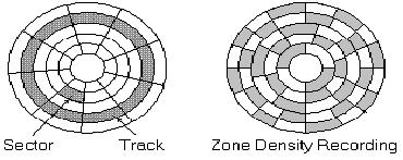
Figure 25–9 Multiple Zones Increase Disk Density
In the above figure, the disk
surface is divided into three zones, each zone having a constant number of
sectors per track
contained. This
allows a better use of linear track density, while maintaining a reasonably
simple disk controller.)
As a simplified example, consider a file containing
1,000–byte records and a disk track with a capacity of 10,000 bytes.
If the blocking factor is 5, one block is 5,000 bytes and you can store two
blocks (ten records) on a track. If the blocking
factor is 6, one block is 6,000 bytes and a track has space for only one block
(six records).
The storage of data on disk begins with the top outermost
track (track 0) and continues consecutively down, surface by
surface, through to the bottom outermost track. Storage of data then continues
with the next inner set of tracks (track 1),
starting with the top track through to the bottom track. The set of vertical
tracks is known as a cylinder.
As a result, for
sequential processing the system reduces access motion of the read/write heads:
It reads and writes blocks, for example,
on track 5 of every surface (cylinder 5) before moving the arm.
DISK ARCHITECTURE
The two main types of IBM disk devices are count–key–data
(CKD) architecture and
fixed–block architecture (FBA). (ELB: There is an
interesting design compromise that appears on later disks, such as
more recent implementations of the IBM 3390 that
continue to use the CKD architecture.
The newer devices implementing
the 3390 architecture are actually large RAID
(Redundant Array of Independent Disks) arrays, each of which implements
the FBA architecture that is common among disks for
commodity computers, such as the Intel x86 and Intel Pentium
servers that are quite common.
The 3390 controller has an interface
that allows it to appear to the Mainframe Computer (such as a z/11) as a CKD
architecture while actually using FBA devices, which
are very reliable, but commodity market, and therefore less expensive.
This design choice shows how IBM has evolved to maintain
its architecture while using commodity items.)
CKD
Architecture
In this design, records and blocks may be of almost any
length, subject to limitations of the disk device. A count (C) area contains
the block size and an optional key (K) area contains the key of the last record
in the block, both of which precede the actual data (D)
area; hence CKD. If a disk contains 20
surfaces, the outer set of tracks (all track 0) is called cylinder 0, the next
inner vertical set of
tracks is cylinder 1, the next is cylinder 2, and so forth. If the
device contains 200 sets of tracks, there are 200 cylinders numbered 0
through 199, each with 20 tracks. If a
disk contains 20 surfaces, each cylinder contains 20 tracks. If the disk contains 200 cylinders,
then each surface contains 200 sets of tracks.
Examples of disk devices using CKD architecture include
IBM models 3330, 3340, 3350, and 3380.
The basic format for a track on a CKD device is
|
Index Point |
Home Address |
Track Descriptor Record |
Data
|
Data |
|
(a) |
(b) |
(c) |
(d) |
|
(a) Index Point. The index point tells the read/write device that this point is the physical beginning of the track.
(b) Home Address. The home
address tells the system the address of the track (the cylinder, head, or
surface number)
and whether the track is primary, alternate, or defective.
(c) Track Descriptor Record (R0).
This record stores information about the track and consists of two separate
fields: a
count area and a data area. The count area contains 0 for record number and 8
for data length and is otherwise similar to
the count area described next for data record under item (d). The data area
contains 8 bytes of information used by the
system. The track descriptor record is not normally accessed by user programs.
(d) Data Record Formats (Rl through Rn). The users' data records, or technically, blocks, consist of the following:
Address Count Key Data
Marker Area Area Area
(optional)
The I/O control unit stores the 2-byte address marker
before each block of data, which it uses subsequently to locate
the beginning of data. The count area
includes the following:
• An
identifier field that provides the cylinder and head number (like that in the
home
address) and the sequential block
number (0-255) in binary, representing R0 through
R255. (The track descriptor record,
R0, contains 0 for record number.)
• The key length (to be explained shortly).
• The data
length, a binary value 0 through 65,535 that specifies the number of bytes in
the
data area field (the length of your
data block). For end–of–file, the system
generates a
last dummy record containing a
length of 0 in this field. When the system reads the file,
the zero length indicates that there
are no more records.
• The
optional key area contains the key, or control field, for the records in the
file, such
as part number or customer number.
The system uses the key area to locate records
randomly. If the key area is
omitted, the file is said to be formatted without keys and is
stored as count-data format. The key
length in the count area contains O. If the file is
formatted with keys, it is stored as
count-data format. The key length in the count area
contains the length of the key area.
• The data area
contains the users' data blocks, in any format, such as unblocked or blocked
and fixed or variable length. The
system stores as many blocks on a track as possible,
usually complete and intact on a
track. A record overflow feature permits the overlapping
of a record from one track to the
next. Figure 25–10 provides the
capacities and speeds
of a number of IBM CKD devices.
Figure 25–11, added in 2009, shows
more modern disks.
Under normal circumstances, you won't be concerned with
the home address, the track descriptor record, or the address
marker, count area, and key area portions of the data record field. You simply
provide appropriate entries in your file
definition macros and job control commands.
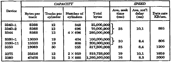
Figure 25–10 Capacity Tables for CKD Devices
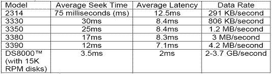
Figure 25–11 DASD Speeds and Data Rates, November 2009
Fixed–Block Architecture
In this
design, the recording tracks contain equal–length blocks of 512 bytes, although
your records and
blocks need not fit a sector exactly. (ELB: This is the format commonly
used by MS–DOS and MS–Windows file systems).
|
Device |
Bytes/block |
Blocks/track |
Number of Cylinders |
Tracks per Cylinder |
Total |
|
3310 |
512 |
32 |
358 |
11 |
64, 520, 192 |
|
3370 |
512 |
64 |
2 of 750 |
12 |
571, 392, 000 |
Disk Capacity
Knowing the
length of records and the blocking factor, you can calculate the number of
records on a track and on a cylinder.
Knowing the number of records, you can also calculate the number of cylinders
for the entire file. Based on the values
in Figure 25–12,
the formula for the number of blocks of data per track is
![]()
In the
formula, C is a constant overhead value for keyed records, KL means Key Length,
and
DL is Data (Block) Length. These values
vary by disk device, as shown below.
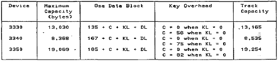
Figure 25-12 Track Capacity Table
The following two examples illustrate.
Example 1: Device is a 3350, records are 242 bytes, five records per block,
(block size =
1,210), and formatted without keys.
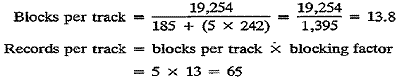
Example 2: Same as Example 1, but formatted with keys (key length is 12).
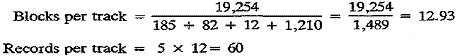
Note that a
disk stores a full block, not a fraction of one. Therefore, even if you calculate 13.8 or 12.9
blocks per
track, the disk stores only 13 or 12 blocks, respectively.
To determine the number of records on a cylinder, refer to
Fig. 25–10, which discloses that a 3350 has 30 tracks per
cylinder. Based on Example 1 where the number of records per track is 65, a
cylinder on the 3350 could contain
65 x 30 = 1,950 records.
Using these figures, you can now calculate how much disk
storage a file of, say, 100,000 of these records would
require. Based on the figure of 1,950 records per cylinder, the file would
require 100,000 ¸
1,950 = 51.28 cylinders.
DISK LABELS
Disks, like magnetic tape, also use labels to identify a
volume and a file. The system reserves cylinder 0,
track 0 for standard labels, as Fig. 25–13 shows.
The following describes the contents of track 0:
Record 0: The track descriptor, R(0) record.
Records 1 and 2:
If the disk is SYSRES, which contains the operating system, certain devices
reserve R(l) and R(2)
for the Initial Program Load (IPL) routine.
For all other cases, R(l) and R(2) contain zeros.
Record 3: The
VOL1 label. OS supports more than one volume label, from
R(3) through R(10).
Record 4 through
the end of the track: The standard location for the volume table of
contents (VTOC). The VTOC
contains the file labels for the files on the device. Although you may place a
VTOC in any cylinder,
its standard location is cylinder 0, track 0.
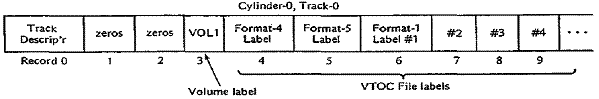
Figure 25–13 Disk Volume Layout
Volume Labels
The standard volume label uniquely identifies a disk
volume. A 4–byte key area immediately precedes the 80–byte
volume data area. The volume label is the fourth record (R3) on cylinder 0. The
80 bytes are arranged like a tape volume
label, with one exception: Positions 12-21 are the "data file
directory," containing the starting address of the VTOC.
File Labels
File labels identify and describe a file, or data set, on
a volume. The file label is 140 bytes long, consisting of a 44–byte
key area and a 96–byte file data area.
Each file on a volume requires a file label for identification. In Fig.
25–13, all file
labels for a volume are stored together in the VTOC. There are four types of
file labels:
1. The format 1 label is equivalent to a file label on
tape. The format 1 label differs, however, in that it defines the actual
cylinder and track addresses of each file's beginning and end (its extent).
Further, a file may be stored intact in an extent
or in several extents in the same volume. Format 3 is used if a file is
scattered over more than three extents.
2. The format 2 label is used for indexed sequential files.
3. The format 3 label is stored if a file occupies more than three extents.
4. The format 4 label is the first record in the VTOC and defines the VTOC for the system.
The format 1 file label contains the following information:
|
Position |
Name |
Description |
|
01 – 44 |
File Identification |
Unique identifier consisting
of the file ID, optional |
|
45 |
Format Identifier |
‘1’ for format 1 |
|
46 – 51 |
File Serial Number |
Volume serial number from the volume label. |
|
52 – 53 |
Volume sequence |
Sequence number if the file
is stored on |
|
54 – 56 |
Creation date |
Three bytes: ydd.
y = year (0 – 99) and |
|
57 – 59 |
Expiration date |
Same as format for creation date. |
|
60 |
Extent count |
Number of extents for this file on this volume. |
|
61 |
Bytes in last block |
Used by OS. |
|
62 |
Unused |
Reserved |
|
63 – 75 |
System code |
Name of the operating system (OS) |
|
76 – 82 |
Unused |
Reserved |
|
83 – 84 |
File Type |
Code to identify is SD
(sequential), DA (direct), |
|
85 |
Record Format |
Used by OS |
|
86 |
Option Codes |
ISAM – indicates if master
index is |
|
87 – 88 |
Block Length |
ISAM – length of each block. |
|
89 – 90 |
Record Length |
ISAM – length of each record. |
|
91 |
Key Length |
ISAM – length of key area. |
|
92 – 93 |
Key Location |
ISAM – position of key within the record |
|
94 |
Data Set |
SD – indicates if last volume |
|
95 – 98 |
Used by OS |
None of your business. |
|
99 – 103 |
Last record pointer |
Used by OS |
|
104 – 105 |
Unused |
Reserved |
|
106 |
Extent type |
Descriptors for the first or
only |
|
107 |
Extent sequence |
|
|
108 – 111 |
Extent lower limit |
|
|
112 – 115 |
Extent upper limit |
|
|
116 – 125 |
|
Descriptors for a second
extent. Same format |
|
126 – 135 |
|
Descriptors for a third extent. Same format as above. |
|
136 – 140 |
Pointer |
Address of the next label. |
KEY
POINTS
• Sequential
file organization provides only for sequential processing of records. Indexed
and
direct organization provides for both
sequential and random processing of records.
• At the
beginning of the tape reel is a volume label, which identifies the reel being
used.
Immediately preceding each file on the
tape is a header label, which contains the name of
the file and the date the file was
created. Following the header label are the records that
comprise the data file. The last record
is a trailer label, which is similar to the header label
but also contains the number of blocks
written on the reel.
• To keep track of all the files it contains, a disk
device uses a special directory (volume table
of contents, VTOC) at the beginning of
its storage area. The directory includes the names
of the files, their locations on disk,
and their present status.
• If you define a tape or disk
field as packed on an IBM system, the field contains
two digits per byte plus a half-byte
for the sign.
• The set of vertical tracks on a disk device is known as a cylinder.
• An interblock
gap (IBG) separates each block of data from the next on tape and disk. The
length of an IBG on tape is 0.3 to 0.6
inches depending on the device, and the length of an
IBG on disk varies by device and by
track location. The IBG defines the start and end of
each block of data and provides space
for the tape when the drive stops and restarts for
each read or write.
• Blocking of
records helps conserve space on storage devices and reduces the number of
input/output operations. The number of
records in a block is known as the blocking factor.
• The system
reads an entire block into the computer's storage and transfers one record
at a time to the program.
• All programs that process a file should use the same record length and blocking factor.
• Records and
blocks may be fixed in length, where each has the same length throughout the
entire file, or variable in length,
where the length of each record and the blocking factor
are not predetermined.
• The two main
types of disk devices are count-key-data (CKD) architecture, which stores
records according to count, key, and
data area, and fixed-block architecture (FBA), which
stores data in fixed-length blocks.