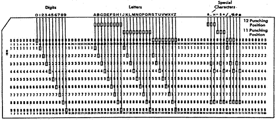
The EBCDIC Character
Set
Here is the set of important
EBCDIC codes.
|
Character
|
Punch Code
|
EBCDIC
|
|
‘0’
|
0
|
F0
|
|
‘1’
|
1
|
F1
|
|
‘9’
|
9
|
F9
|
|
‘A’
|
12
– 1
|
C1
|
|
‘B’
|
12
– 2
|
C2
|
|
‘I’
|
12
– 9
|
C9
|
|
‘J’
|
11
– 1
|
D1
|
|
‘K’
|
11
– 2
|
D2
|
|
‘R’
|
11
– 9
|
D9
|
|
‘S’
|
0
– 2
|
E2
|
|
‘T’
|
0
– 8
|
E3
|
|
‘Z’
|
0
– 9
|
E9
|
Note that the EBCDIC codes for the digits ‘0’ through ‘9’ are
exactly the zoned decimal representation of those digits. (But see below).
The DS declarative is used to reserve storage for character data, while
the DC declarative is used to
reserve initialized storage for character data.
There are constraints on character declarations, which apply to both the
DS and DC declaratives.
1. Their
length may be defined from 1 to 256 characters.
As a practical matter, long
character constants should be avoided.
2. They
may contain any character. Characters
not available in the standard
set may be introduced by
hexadecimal definitions.
3. The
length may be defined either explicitly or implicitly.
It is usually a good idea
not to do both, as this can lead to mistakes.
Consider the case in which a DC
declarative is used to define a character constant. If the length attribute is specified, it
overrides the length implied by the constant itself. Remember that the length is really a byte
count, which is the same as a character count.
The following examples will illustrate the issues of both explicit and
implicit length definitions.
MONTH1 DC CL6‘SEPTEMBER’ STORED AS ‘SEPTEM’
MONTH2 DC CL6‘MAY’ STORED AS ‘MAY ’
MONTH3 DC CL6‘AUGUST’ STORED AS ‘AUGUST’
In the first case, the explicit
length is less than the actual length of the constant, so that the value stored
is truncated after the explicit length is stored. The rightmost characters are lost.
In the second case, the explicit
length is greater than the actual length of the constant. The value stored is padded with blanks out to
the specified explicit length; here 3 are added.
It should be obvious that
nothing special happens when the explicit length is exactly the same as the
length of the constant. There may be
reasons to do this, possibly for documentation.
Defining Character
Strings
While the term “string” is not
exactly appropriate in this context, we need some way to speak of a sequence of
characters such as defined above. In the
IBM parlance, the sequence defined by the declarative DC CL6‘AUGUST’ is
viewed as character data. Strictly
speaking, this is a sequence of six characters.
We shall speak of general string
handling in a later chapter. The issue
at this point is how the assembler determines the length of the string when
executing an instruction such as MVC. The answer is that each such instruction
specifically encodes the length of the string to be processed. Again, it is the instruction that really
defines the length and not the declaration.
Examination of the object code
for these character instructions will show that the length is stored in
modified form as an 8–bit unsigned integer.
Actually, the length is decremented by one before it is stored. The range of an 8–bit unsigned integer is 0
through 255 inclusive, so that the length that can be stored ranges from 1
through 256. There seems to be no
provision for zero length sequences of characters. Zero length strings will be discussed in a
later chapter in which the entire idea of a string will be fully developed.
First, let’s recall one major
difference between the DS and DC declaratives.
The DS may appear to initialize storage, but it does not. Only the DC initializes storage. The difference is illustrated by considering
the following two declarations.
V1 DS CL4‘0000’ Define four bytes of uninitialized
storage. The ‘0000’ is just a comment.
The four bytes
allocated will have some
value, but that is
unpredictable.
V2 DC CL4‘0000’ Define four bytes of storage, initialized
to the four bytes F0
F0 F0 F0, which
represent the four
characters.
One should use the DS
declaration only for fields that will be initialized by some other means, such
as the MVC instruction that is discussed below.
It is always possible to move values into an area of memory initialized
with a DC declarative. In the above
example, it is possible to move the character constant ‘2222’ to V2, which
would then contain that value.
The student should also note
that it is very easy to write the above declarations in a form that might cause
assembly errors. Consider the following
two declarations.
V3 DS CL4 ‘0000’ Define four bytes of uninitialized
storage. Note the blank after ‘CL4’.
Since everything
after the ‘CL4’ is a
comment, this does
not cause a problem.
V4 DC CL4 ‘0000’ This causes an assembly error. The DC
declarative exists
to initialize the
storage area, but
the blank after the
‘CL4’ introduces a
comment. The ‘0000’
is not recognized
as a value.
Note that no declaration above
actually defines a number, but just a sequence of characters that happen to be
digits.
Explicit Base Addressing for Character Instructions
We now
discuss a number of ways in which the operand addresses for character
instructions may be presented in the source code. One should note that each of these source
code representations will give rise to object code that appears almost
identical. These examples are taken from
Peter Abel [R_02, pages 271 – 273].
Assume that
general–purpose register 4 is being used as the base register, as assigned at
the beginning of the CSECT. Assume also that the following statements
hold.
1. General
purpose register 4 contains the value X‘8002’.
2. The
label PRINT
represents an address represented in base/offset form as 401A; that
is it is at offset X‘01A’
from the value stored in the base register, which is R4.
The address then is X‘8002’
+ X‘01A’
= X‘801C’.
3. Given
that the decimal number 60 is represented in hexadecimal as X‘3C’,
the address PRINT+60
must then be at offset X‘01A’ + X‘3C’ = X‘56’
from
the address in the base
register. X‘A’ + X‘C’,
in decimal, is 10 + 12 = 16 + 6.
Note that this gives the address of PRINT+60
as X‘8002’
+ X‘056’
= X‘8058’,
which is the same as X‘801C’
+ X‘03C’. The sum X‘C’ + X‘C’, in decimal, is
represented as 12 + 12 = 24 =
16 + 8.
4. The
label ASTERS
is associated with an offset of X‘09F’ from the value in the
base register; thus it is
located at address X‘80A1’. This label references a storage
of two asterisks. As a decimal value, the offset is 159.
5. That
only two characters are to be moved by the MVC instruction examples to be
discussed. Since the length of the move destination is
greater than 2, and since the
length of the destination is
the default for the number of characters to be moved, this
implies that the number of
characters to be moved must be stated explicitly.
The first
example to be considered has the simplest appearance. It is as follows:
MVC PRINT+60(2),ASTERS
The
operands here are of the form Destination(Length),Source.
The destination is the address
PRINT+60. The length (number of characters
to move) is 2. This will be encoded in the length byte as X‘01’,
as the length
byte stores one less than the
length. The source is the address ASTERS.
As the MVC
instruction is encoded with opcode X‘D2’, the object code here is as
follows:
|
Type
|
Bytes
|
Operands
|
1
|
2
|
3
|
4
|
5
|
6
|
|
SS(1)
|
6
|
D1(L,B1),D2(B2)
|
OP
|
L
|
B1 D1
|
D1D1
|
B2 D2
|
D2D2
|
|
|
|
|
D2
|
01
|
40
|
56
|
40
|
9F
|
The next few examples are given to remind
the reader of other ways to encode
what is essentially the same instruction.
These
examples are based on the true nature of the source code for a MVC
instruction, which is MVC D1(L,B1),D2(B2). In this format, we have the following.
1. The
destination address is given by displacement D1 from the address
stored in
the base register indicated by
B1.
2. The
number of characters to move is denoted by L.
3. The
source address is given by displacement D2 from the address stored in
the base register indicated by
B2.
The second
example uses an explicit base and displacement representation of the
destination address, with general–purpose register 8 serving as the explicit
base register.
LA R8,PRINT+60
GET ADDRESS PRINT+60 INTO R8
MVC 0(2,8),ASTERS MOVE THE CHARACTERS
Note the
structure in the destination part of the source code, which is 0(2,8).
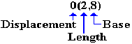
The
displacement is 0 from the address X‘8058’, which is stored in
R8. The object code is:
|
Type
|
Bytes
|
Operands
|
1
|
2
|
3
|
4
|
5
|
6
|
|
SS(1)
|
6
|
D1(L,B1),D2(B2)
|
OP
|
L
|
B1 D1
|
D1D1
|
B2 D2
|
D2D2
|
|
|
|
|
D2
|
01
|
80
|
00
|
40
|
9F
|
The instruction could have been written
as MVC
0(2,8),159(4), as the label
ASTERS is found at offset 159 (decimal) from the address in register 4.
The third example uses an explicit base
and displacement representation of the destination address, with
general–purpose register 8 serving as the explicit base register.
LA R8,PRINT
GET ADDRESS PRINT INTO R8
MVC 60(2,8),ASTERS SPECIFY A DISPLACEMENT
Note the
structure in the destination part of the source code, which is 60(2,8).
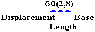
The
displacement is 60 from the address X‘801C’, stored in R8. The object code is:
|
Type
|
Bytes
|
Operands
|
1
|
2
|
3
|
4
|
5
|
6
|
|
SS(1)
|
6
|
D1(L,B1),D2(B2)
|
OP
|
L
|
B1 D1
|
D1D1
|
B2 D2
|
D2D2
|
|
|
|
|
D2
|
01
|
80
|
3C
|
40
|
9F
|
The instruction could have been written
as MVC
60(2,8),159(4), as the label
ASTERS is found at offset 159 (decimal) from the address in register 4.
Sample Declarations
We now give a few examples of
declarations of character constants.
These examples will appear in the form of an assembler listing. Each line will have four parts: a location,
the object code (EBCDIC characters) that would be generated, the declaration
itself, and then some comments in the field that the assembler would reserve
for comments.
LOC
Obj. Code Source Code Comments
005200 40404040
B1 DC CL4‘ ’ FOUR BLANKS
005204 40404040
B2 DC 4CL1‘ ’ FOUR SINGLE
BLANKS. NOTE
THE IDENTICAL OBJECT CODE.
005208 F0F0F0F0
Z1 DC C‘0000’ FOUR DIGITS
00520C F2F2F2F2
N2 DC 4CL1‘2’ FOUR MORE DIGITS
The MVC Instruction
The MVC
(Move Character) instruction is designed to move character data, but it can be
used to move data in any format, one byte at a time. As we shall see later, the MVC can be used to
move packed decimal data, but this is not advised as strange errors can occur.
The MCV
instruction is a storage–to–storage (type SS) instruction. The opcode is X‘D2’.
The
instruction may be written as MVC
DESTINATION,SOURCE
An
example of the instruction is MVC
F1,F2
The
format of the instruction is MVC
D1(L,B1),D2(B2). This format
reflects the fact that each of the source and destination addresses is
specified by a base register (often the default base register) and a
displacement. Here is the format of the
object code.
|
Type
|
Bytes
|
Form
|
1
|
2
|
3
|
4
|
5
|
6
|
|
SS(1)
|
6
|
D1(L,B1),D2(B2)
|
X‘D2’
|
L
|
B1
D1
|
D1D1
|
B2
D2
|
D2D2
|
Here are a few comments on MVC.
1. It
may move from 1 to 256 bytes, determined by the use of an 8–bit number
as a length field in the
machine language instruction.
The destination length is first
decremented by 1 and then stored in the length byte,
which can store an unsigned
integer representing values between 0 and 255.
This disallows a length of
0, and allows 8 bits to store the value 256.
2. Data
beginning in the byte specified by the source operand are moved one
byte at a time to the field
beginning with the byte in the destination operand.
One of the reasons for complexity
of the implementation is that the source
and destination regions may
overlap.
3. The
length of the destination field determines the number of bytes moved.
Example of the MVC Instruction
Consider
the example assembly language statement, which moves the string of
characters at label CONAME to the location associated
with the label TITLE.
MVC TITLE,CONAME
Suppose
that: 1. There are fourteen bytes associated with TITLE, say that it
was
declared
as TITLE
DS CL14. Decimal 14 is
hexadecimal E.
2. The label TITLE is referenced by
displacement X‘40A’
from the value stored in register R3,
used as a base register.
3. The label CONAME is referenced by
displacement X‘42C’
from the value stored in register R3,
used as a base register.
Given that the
operation code for MVC is X‘D2’, the instruction assembles
as
D2
0D 34 0A 34 2C Length is 14 or X‘0E’; L
– 1 is X‘0D’
To be
totally obvious with this example, let us disassemble the object code that we
have just created by manual assembly.
The only assumption at the start is that the byte with value
X‘D2’
contains the opcode for the instruction.
Here again is the object code format.
|
Type
|
Bytes
|
Form
|
1
|
2
|
3
|
4
|
5
|
6
|
|
SS(1)
|
6
|
D1(L,B1),D2(B2)
|
X‘D2’
|
L
|
B1
D1
|
D1D1
|
B2
D2
|
D2D2
|
The opcode X‘D2’ is that for
the MVC instruction (surprise!). This is
a type SS instruction which has a total of six bytes: the opcode byte and five
bytes following.
The
second byte contains the length field.
Its value is X‘0D’, representing the decimal
value 13. This is one less than the
length of the destination field, which must have length 14.
Bytes 3
and 4 represents an address, expressed in base/displacement format, as do bytes
5 and 6. The value in bytes 3 and 4 is a
16–bit number, in hexadecimal it is X‘340A’.
This indicates that general purpose register 3 is being used as the
base for this address and that the offset is given by X‘40A’. Suppose that register 3 contains the value X‘1700’. The address represented would then be X‘1700’
+ X‘40A
= X‘1B0A’.
MVC: Explicit Register Usage
The
instruction may be written explicitly in the form MVC D1(L,B1),D2(B2)
Consider
the following example: MVC 32(5,7),NAME. In this example, suppose that general–purpose
register 7 has the value X‘22400’. We note that the label NAME represents an
address that will be converted to the form D2(B2); that is, a displacement
from a base register. This base register
might be register 7 or any of the ten registers (R3 – R12) available for
general use.
We
examine the specification of the first argument, which is the destination
address.
It is of the form D1(L,B1). The length is L = 5. This indicates that five characters are to be
moved. The displacement is decimal 32,
or X‘20’.
The
address of the first character in the destination is given by adding this
displacement
to the contents of the base register: X‘22400’ + X‘20’ = X‘22420’. Five characters are moved to the
destination. The fifth character is
moved to a location that is four bytes displaced from the first character; its
address is X‘22424’.
Suppose
that the label NAME corresponds to an address given by offset X‘250’(592
in
decimal) from general–purpose register 10 (denoted in object code by X‘A’).
When the
instruction is written in the form MVC D1(L,B1),D2(B2), we see that it
has the form MVC 32(5,7),592(10). ALL
NUMBERS ARE DECIMAL.
In
the object code format, the value stored for the length attribute is one less
than
the actual length. The length is 5, so
the stored value is 4, or X‘04’.
The
object code format is D2 04 70 20 A2 50.
Again,
recall the object code format for this instruction.
|
Op Code
|
Length
|
Base
|
Displacement
|
Base
|
Displacement
|
|
D
|
2
|
0
|
4
|
7
|
0
|
2
|
0
|
A
|
2
|
5
|
0
|
|
|
|
|
|
|
|
|
|
|
|
|
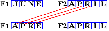
MVC: Example of Length Mismatch
The
number of bytes (characters) to move may be explicitly stated in the source
statement. However if it is not explicitly
stated, the number is taken as the length (in bytes or characters) of the
destination field. Consider the
following program fragment.
MVC F1,F2
F1 DC CL4‘JUNE’
F2 DC CL5‘APRIL’
What
happens is shown in the next figure.
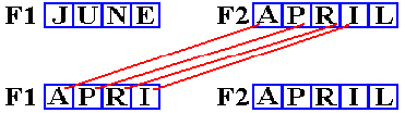
The
assembler recognizes F1 as a four–byte field from its declaration by the DC
statement. This implicitly sets the
number of characters to be moved. The character
‘L’ is not moved, as it is the fifth character in F2. It is at address F2+4.
MVC: Another Example
of Length Mismatch
The
number of bytes (characters) to move may be explicitly stated in the source
code. While the explicit length may
exceed that of the destination field, your instructor (but not many textbook
authors) considers that bad programming practice.
Consider
the following program fragment, in which an explicit length of 3 is set. Recall the form of the instruction: MVC D1(L,B1),D2(B2).
MVC F1(3),F2 The (3) says move three characters
F1 DC CL4‘JUNE’
F2 DC CL5‘APRIL’
What
happens is shown in the next figure.
Note that
only “APR” is moved. The last character
of F1, which is an “E”, is not changed.
This last character is at address F1+3.
MVC: Example 3
We may
use relative addressing as well as an explicit length declaration. Consider the following program fragment.
MVC F1+1(2),F2+2
F1 DC CL4‘JUNE’
F2 DC CL5‘APRIL’
This
calls for moving two characters from address F2+2 to address F1+1. The two characters at address F2+2
are “RI”. The two characters at the destination address
F1+1
are “UN”. What happens is shown in the next figure.
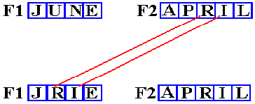
The other
two characters in F1, at addresses F1 and F1+3, are not
changed.
MVC: Example 4
We now
consider the explicit use of base registers.
Recall
the form of the instruction: MVC
D1(L,B1),D2(B2).
In the
following three examples, we suppose that PRINT is a label associated with
an output field of length 80 bytes. In
reality, it only must be “big enough”.
FRAG01 MVC PRINT+60(2),=C‘**’
FRAG02 LA
R8,PRINT+60 LOAD THE ADDRESS.
MVC 0(2,8),=C‘**’ DEST
ADDRESS IS PRINT+60
FRAG03 LA
R8,PRINT LOAD THE
ADDRESS.
MVC 60(2,8),=C‘**’ NOTE OFFSET IS 60
Suppose
that the address of PRINT is given by base register 12
and displacement X‘200’.
Suppose register 12 contains a value of X‘1000’. The label PRINT
references address X‘1200’. The value of PRINT+60 is then X‘1200’
+ X‘60’
= X‘1260’.
As an
aside, note that it appears more natural to write the first instruction in the
form.
FRAG01 MVC PRINT+60(2), =C‘**’
Note that
there is a space following the comma.
This space turns whatever fallows it into a comment, thus rendering the
instruction incomplete and erroneous.
Describing Input Fields
Consider
the following block that declares area for an 80–column input (corresponding to
an 80–column punch card) that is divided into fields.
Here
is a declaration of an 80–byte input area that will be divided into fields.
CARDIN
DS 0CL80 The record has 80 bytes.
NAME
DS CL30 The first field has the name.
YEAR
DS CL10 The second field.
DOB
DS CL8 The third field.
GPA
DS CL3 The fourth field.
DS CL29
The last 29 chars are not used.
The
address corresponding to the label NAME is the same as that for the
label CARDIN. The field NAME corresponds to
addresses NAME
through NAME+29,
inclusive.
The
address corresponding to the label YEAR is the same as the address CARDIN+30. The field YEAR corresponds to
addresses YEAR
through YEAR+9,
inclusive. Equivalently, the field
corresponds to addresses CARDIN+30 through CARDIN+39,
inclusive.
Relative
addressing will often be used to extract fields from an input record or place
fields into an output record.
Character Comparison:
CLC
The CLC (Compare Logical Character) instruction
is one of the two used to compare
character fields, one byte at a time, left to right.
Comparison
is based on the binary contents (EBCDIC code) contents of the bytes.
The sort order is from X’00’ through X’FF’.
The
instruction may be written as CLC
Operand1,Operand2
The
format of the instruction is CLC
D1(L,B1),D2(B2)
An
example of the instruction is CLC
NAME1,NAME2
This
instruction sets the condition code that is used by the conditional branch instructions. The condition code is set as follows:
If
Operand1 is equal Operand2 Condition
Code = 0
If
Operand1 is lower than Operand2 Condition Code = 1
If
Operand1 is higher than Operand2 Condition Code = 2
The
operation moves, byte by byte, from left to right and terminates as soon as an unequal
comparison is found or one of the operands runs out.
Using the Condition
Codes
The
character comparison operators, CLC and CLI, set the condition codes. These codes are used by the branching
instructions in their non–numeric form. Here
are the standard comparisons.
BE Branch
Equal Condition Code = 0
BNE Branch
Not Equal Condition Code ¹ 0
BL Branch
Low Condition Code = 1
BNL Branch
Not Low Condition Code ¹ 1
BH Branch
High Condition Code = 2
BNH Branch
Not High Condition Code ¹ 2.
Here are
two equivalent examples.
CLC X,Y
BL
J20LOEQ X sorts less than Y
BE J20LOEQ Y is equal to Y
CLC X,Y
BNH J20LOEQ X does not sort higher than Y
CLC: An Example
Consider
the following code fragment. Note that
the comparison value is given
as the seven EBCDIC characters ‘0200000’.
Presumably,
this would be converted into seven Packed Decimal digits and held to
represent the fixed point number 2000.00, presumably $2,000.00.
C20 CLC SALPR,=C‘0200000’ COMPARE TO 2,000.00
BNH C30 NOT ABOVE 2,000.00
BL
C40 LESS THAN
2,000.00
* EQUAL TO 2,000.00
Again,
this is presented as representing Packed Decimal data, which it probably
does represent. The comparison, however,
is an EBCDIC character comparison.
Here is
another example, built around the first one.
It represents an important
special case that we shall consider when discussing Packed Decimal format.
C20 CLC
SALPR,=C‘ ’ IS THE FIELD BLANK?
BNE
NOTBLNK
MVC
SALPR,=C‘0000000’ CONVERT
BLANKS TO 0’S
NOTBLANK
PACK SALNUM,SALPR
MVI and CLI
These two
operations are similar to their more general “cousins”, except
that the second operand is a one–byte immediate constant.
The immediate constant may be
of any of the following formats:
B binary
C character
X hexadecimal
The format of these
instructions are: MVI Operand1,ImmediateOperand
CLI
Operand1,ImmediateOperand
Examples of these
instructions are: MVI
CONTROL,C’$’ Character ‘$’
CLI CODE,C’5’ Character ‘5’
Character Literals
vs. Immediate Operands
The main
characteristic of an immediate operation is that the operand, called the“immediate
operand” is contained within the instruction. The main characteristic of a
literal operand is that it is stored separately from the operand, in a literal
pool generated by the assembler.
Here are
two equivalent instructions to set the currency sign.
Use of a
literal: MVC
DOLLAR,=C’$’
Use of
immediate operand MVI
DOLLAR,C’$’
Note the “=”
in front of the literal. It is not
present in the immediate operand.
Insert Character (IC) and Store Character (STC)
The IC
instruction moves a single byte (8 bits) from storage into a register and the
STC moves a byte from the register to storage.
Each access only the rightmost 8 bits of the general purpose register,
denoted as bits 24 through 31.
Each of the
instructions is a type RX instruction of the form OP REG,MEMORY. Note that:
1. The
first operand denotes a general purpose register, of which only the rightmost
8 bits (24 – 31) will be used.
2. The
second operand references one byte in storage, as each EBCDIC
character is stored in a
single byte. As this is a byte address,
there are no
restrictions on its value; it
can be an even or odd number.
The
opcode for IC is X‘43’, while that for STC is X‘42’. The object code is of the form OP
R1,D2(X2,B2).
|
Type
|
Bytes
|
Operands
|
1
|
2
|
3
|
4
|
|
RX
|
4
|
R1,D2(X2,B2)
|
OP
|
R1
X2
|
B2
D2
|
D2D2
|
The first byte contains the
8–bit instruction code, either X‘42’ or X‘43’.
The
second byte contains two 4–bit fields, each of which encodes a register number. The field R1 denotes the general
purpose register that is either the source or destination of the transfer. The field X2 denotes the optional
index register to be used in address calculation.
The
third and fourth bytes hold the standard base/displacement address.
The IC
instruction does not change the three leftmost bytes (bits 0 – 23) of the
register being loaded. The STC
instruction does not use these three bytes.
Case Conversion
We now
present an interesting use for these two instructions. This is the conversion of alphabetical
characters from upper case to lower case and back again. In order to do this, we need a few
instructions that have yet to be discussed.
The three
instructions are here given in their immediate format, though there are other
forms that will be discussed later.
These are logical AND, logical OR, and logical XOR. Each of these operations is a bitwise
operation, defined as follows.
AND 0·0 = 0 OR 0+0 = 0 XOR 0Å0 = 0
0·1 = 0 0+1 = 1 0Å1 = 1
1·0 = 0 1+0 = 1 1Å0 = 1
1·1 = 1 1+1 = 1 1Å1 = 0
The three
instructions, as implemented in the S/370 architecture, are as follows:
NI Logical
AND Immediate Opcode X‘92’
OI Logical
OR Immediate Opcode X‘96’
XI Logical
XOR Immediate Opcode X‘97’
Each
instruction is type SI, and is written as source code in the form OP
TARGET,MASK.
The indicated operation is applied to the TARGET and the result stored in
the TARGET.
Another Look at Part of the EBCDIC Table
In order
to investigate the difference between upper case and lower case letters, we here present a slightly different version
of the EBCDIC table.
|
|
Zone
|
8
|
C
|
9
|
D
|
A
|
E
|
|
Numeric
|
|
|
|
|
|
|
|
|
1
|
|
“a”
|
“A”
|
“j”
|
“J”
|
|
|
|
2
|
|
“b”
|
“B”
|
“k”
|
“K”
|
“s”
|
“S”
|
|
3
|
|
“c”
|
“C”
|
“l”
|
“L”
|
“t”
|
“T”
|
|
4
|
|
“d”
|
“D”
|
“m”
|
“M”
|
“u”
|
“U”
|
|
5
|
|
“e”
|
“E”
|
“n”
|
“N”
|
“v”
|
“V”
|
|
6
|
|
“f”
|
“F”
|
“o”
|
“O”
|
“w”
|
“W”
|
|
7
|
|
“g”
|
“G”
|
“p”
|
“P”
|
“x”
|
“X”
|
|
8
|
|
“h”
|
“H”
|
“q”
|
“Q”
|
“y”
|
“Y”
|
|
9
|
|
“i”
|
“I”
|
“r”
|
“R”
|
“z”
|
“Z”
|
The structure implicit in the above
table will become more obvious when we compare
the binary forms of the hexadecimal digits used for the zone part of the code.
Upper
Case C = 1100 D = 1101
E = 1110
Lower Case 8 = 1000 9 = 1001
A = 1010
Note that
it is only one bit in the zone that differentiates upper case from lower case.
In binary, this would be noted as 0100 or X‘4’. As this will operate on the zone field of a
character field, we extend this to the two hexadecimal digits X‘40’. The student should verify that the
one’s–complement of this value is X‘BF’. Consider the following operations.
UPPER CASE
‘A’ X’1100
0001’ X’1100
0001’
OR X ‘40’ X‘0100 0000’ AND X ‘BF’ X‘1011 1111’
X’1100 0001’ X’1000 0001’
Converted
to ‘A’ ‘a’
Lower case
‘a’ X’1000
0001’ X’1000
0001’
OR X ‘40’ X‘0100 0000’ AND X ‘BF’ X‘1011 1111’
X’1100 0001’ X’1000 0001’
Converted
to ‘A’ ‘a’
We now
have a general method for changing the case of a character, if need be.
Assume that the character is in a one byte field at address LETTER.
Convert a character to upper
case. OI,LETTER,=X‘40’
This
leaves upper case characters unchanged.
Convert a character to lower
case. NI,LETTER,=X‘BF’
This
leaves lower case characters unchanged.
Change
the case of the character. XI,LETTER,=X‘40’
This changes upper case to lower case and lower case to upper case.