The IBM 370
Programming Environment
This lecture is a “trip down
memory lane”, designed to explain the software
development environment in which the IBM 360 and OS/360 were developed.
The IBM 360 is the immediate
predecessor of the IBM 370, which itself is
the indirect predecessor of every existing IBM Mainframe computer.
There are many factors that can
be seen implicitly in the design of
the assembly language. It is helpful to
point these out.
We begin with the structure of
typical I/O devices:
punched card readers,
punched card punches, and
line printers.
We continue with a discussion
of the “label rich” environment associated
with a typical assembly language program and show tricks to make that more
structured.
We then shall discuss the
original structured programming movement and its
origins in the development of OS/360 – the operating system for the IBM 360.
Punched
Cards
When the IBM 360 was first
designed, most data input was from 80–column
punched cards. IBM experimented with
other formats, but they never caught on.
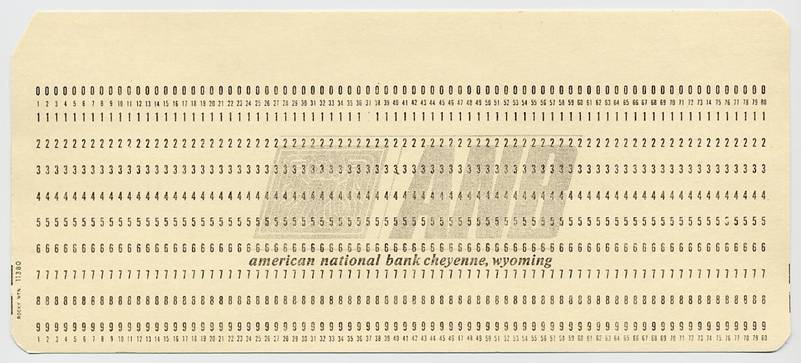
Here is the picture of a
typical 80–column punched card.
It has 12 rows, ten rows labeled 0 – 9, and two unlabeled rows at the top.
Punched
Cards (Part 2)
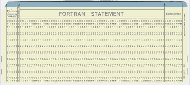
Here is a card with column
markings appropriate for FORTRAN programs.
Again, it has 12 rows, ten of which are labeled.
Note the division of columns
into fields appropriate for the language
Columns 1 – 5: Either a “C” for comment or a five digit
statement label
Column 6: Any nonblank character to indicate a continuation card
Columns 7 – 72: The FORTRAN statement
Columns 73 – 80: The card’s collating sequence.
A Few Notes
on Assembler and FORTRAN
Though distinctly different
languages, Mainframe Assembler and
FORTRAN (developed by IBM in the 1950’s) share a common heritage.
1. Each programming language statement is expected to be one line
long.
Multiple–line statements must be
indicated by a continuation character.
For FORTRAN, any nonblank character in column 6 indicates
that the
present line is a continuation of
the previous line of code, on the previous card.
For Mainframe Assembler, any nonblank character in column 72
indicates
that the next line is a
continuation of the present line.
2. The FORTRAN cards have an eight–digit sequence number in columns
73 – 80.
These were optionally used to
identify the program and the card’s
position in that program.
If the card deck was dropped, the cards could be placed in a
special
card sorter and restored to the
proper order.
3. Occasionally, the text printed on the top line of the card did
not reflect
accurately the punch codes in the
12 rows of the card.
This could cause significant problems in debugging a program.
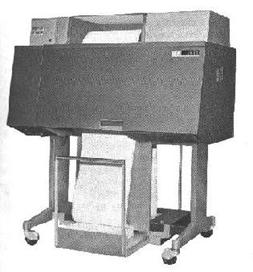
The IBM 029
Key Punch
Here is a picture of the device
used to produce punched data cards.
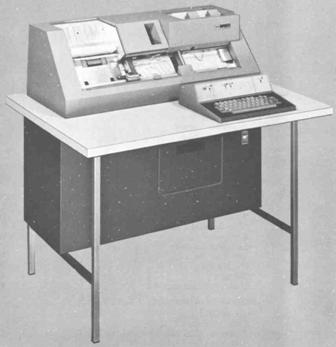
The card feed was at the right.
The card moved right–to–left as
it was punched.
The punched cards were stored
in a tray at the top left.
IBM 029
Punch Card Codes
Here is a card punched with
each of the 64 characters available under this format.
Note the lack of lower case letters; the IBM Mainframe assembler reflects this.
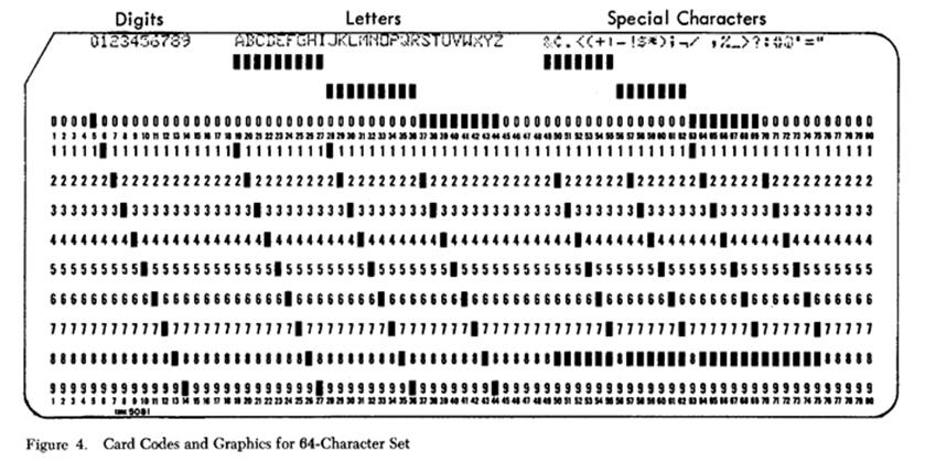
The codes are given by rows: A
is 12–1, K is 11–2, S is 0–2, etc.
Digits were punched in a single row: the row is the number.
Back to
EBCDIC
Consider the IBM 029 punch
codes and compare them to the EBCDIC.
|
Character |
EBCDIC |
Punch Card Codes |
|
0 through 9 |
F0 through F9 |
0 through 9 |
|
A through I |
C1 through C9 |
12–1 through 12–9 |
|
J through R |
D1 through D9 |
11–1 through 11–9 |
|
S through Z |
E2 through E9 |
0–2 through 0–9 |
This table explains the design
of the EBCDIC system.
1. IBM chose this
design for ease in processing input
from existing devices,
such as the IBM 029 key punch.
2. The gaps in the
EBCDIC system: no character from the 64 character set
has a non–decimal digit as
its second digit.
Cards did not have rows marked A, B, C, D, E, or F.
Fields,
Records, and Files
Given our discussion of punched
cards, the section “Fields, Records, and Files” on
page 18 of the textbook comes into better focus.
The preferred 80–character form
of a record reflects immediately the
heritage from 80–column punched data cards as input.
The IBM terminology here is
rather standard.
A file is seen as a collection
of related records, preferably records of the same kind.
A record is a collection of one
or more related fields.
There is no requirement for the fields to represent the same kind of data.
Some fields may be character data, some numeric data, and some structured data.
A field containing structured
data might contain subfields. A date
field should contain the month, day, and year as subfields.
NOTE: The sample record in Figure 2–1 on page 18 must have been created
in
the days before relational
databases.
The modern practice would be to
split this into two records in different tables.
1. The
customer ID, customer name, and customer address
2. The customer ID and customer balance.
Common
Output Formats
There are two common data
formats seen in the time of the IBM 370.
These are 80 column and 132 column outputs.
Quite often, the first
character output would be used to control the print device.
For this reason, an 80 column output might have 81 characters, etc.
The 80–column output was used
by devices such as the console printer,
a modified teletype device.
The 132–column output was used
by devices such as a line printer.
 The device at
left is an IBM 1403 line printer.
The device at
left is an IBM 1403 line printer.
It used a print chain to print
132 column output.
As the output involved
mechanical action of the print
chain, the device produced a very audible sound as it printed.
One popular hobby of the
computer geeks was to devise
output sequences that would cause the printer to play music.
A sample: Raindrops
Keep Falling On My Head.
Page printers and laser
printers date from much later.
Fixed Format
Statements
Unlike the free–format modern
programming languages, the early languages such as FORTRAN and Mainframe
assembler had a fixed format.
A fixed format simplifies the
design of the compiler and/or assembler.
Here is the format suggested
for Mainframe Assembler.
Columns 1 – 8: Statement label.
If column
1 contains an “*”, the line is a comment.
Column 9: Blank. This contains nothing.
Columns 10 – 14: The assembly language operation.
This must
be followed by at least one blank position.
Columns 16 – 71: The operand or operands.
The count
of operands depends on the operation.
Multiple
operands are separated by commas with no spaces.
The first blank not in quotes
following the operand list
begins an
in–line comment that follows the instruction
Column 72: Continuation character; the next
line continues this one.
Managing
Labels
Older assembly languages, such
as IBM Mainframe Assembler, require the use of
a large number of statement labels.
This requirement is due to the
lack of higher–level structures, such as most looping
constructs, if–then–else constructs, break statements, etc.
On page 46 of the textbook, our
author suggests one strategy for
managing the complexity associated with many labels.
The author suggests a “sort
order” for labels, so that code lines later in
the program have labels that sort after labels for lines that occur earlier.
1. Each program is
to be divided into logical sections.
2. The program code
with each section is to be associated with a letter.
Labels for that section
begin with that letter.
3. The next two
characters in the label are to be digits, increasing by
intervals of 10: A10, A20,
A30, etc.
4. The next 1 to 5
characters are indicated by a name descriptive
of the function performed
by this section of code.
Since labels are sequential,
they are easier to locate.
Software
Engineering
The IBM System/360 was
developed as a joint hardware/software project.
Along with the “big iron”, IBM
developed also compilers, assemblers,
and an operating system, OS/360. For
more details, see the Wikipedia
reference.
The OS/360 project quickly got
out of hand. Among the other problems,
it
was too larger to fit into the limited memory of the smaller System/360 models.

Fred Brooks was the manager for
OS/360 development. As a result of his
experiences, he formulated Brook’s law: “Adding manpower to a late software
project makes it later”. He also coined
the slogan “No silver bullet”.
He also wrote the book The
Mythical Man–Month: Essays on Software Engineering.
The cover of that book is shown
at left. It depicts prehistoric
creatures becoming trapped in the La Brea tar pit, now within the city of
Structured
Programming
The term “structured programming” dates from the earliest days of the
software engineering movement, some time in the mid 1960’s.
As described in our textbook,
structured programming has a number
of stages that are to be undertaken sequentially.
1. Problem analysis.
Here
one defines the problem and discusses the solution with the customer.
2. Data design
For
commercial products, this involves considerable design of forms for
the input and output of
data. IBM developed a tool, called HIPO,
for this.
For COBOL programs, this is the time to lay out the
data sections.
3. Logic design
Here
the logic of the program is defined.
High–level tools should be
used to specify the design
before code is written. This is
“structured design”.
4. Coding
Here
the code is written. In higher–level
languages, the constructs used should
be those of structured
programming: sequence, repetition, and selection.
Most assembly languages do
not support these constructs.
Coupling and
Cohesion
The ideas of coupling and cohesion were developed by the structured programming
movement and have persisted into the more modern methods, such as
Object–Oriented Analysis and Design.
The ideas here are quite
simple: 1. Modules should be highly cohesive, and
2. Any pair of modules should be loosely
coupled.
Cohesion
A
module with optimal cohesion performs only one function.
A module with acceptable
cohesion is a collection of procedures to perform related functions. An example would be a trigonometry package
calculating the sine, cosine, and tangent of angles as well as converting
between degrees and radians.
A module with incidental
cohesion is one containing a random collection of procedures.
Coupling
Modules
with low coupling exchange data only through argument lists or not at all.
Modules with common coupling
exchange data through shared global data spaces.
Modules with tight coupling
have direct access to each other’s local variables.
The
design goal is to have highly cohesive modules with low coupling among them.
Comments and
Documentation
Well documented code makes use
of a number of tactics.
The most obvious is the use of descriptive names for variables and
statement labels.
Judicious use of comments will
greatly improve the readability of the code.
Some comments should be viewed as section headers,
telling what the next section of code does.
Some comments are
worthless. Here are two examples
AR 1,2 Add
register 2 to register 1
A10 DC F’1827’ RIP LVB
The last example is from a real
program. This comment was the only one
in the code.
What do you think it signifies?