Type RS Instruction Format
This is a four–byte instruction of the form OP R1,R3,D2(B2).
|
Type |
Bytes |
Operands |
1 |
2 |
3 |
4 |
|
RS |
4 |
R1,R3,D2(B2) |
OP |
R1 R3 |
B2 D2 |
D2D2 |
The first byte contains the 8–bit instruction code.
The second byte contains two 4–bit fields, each of which encodes a register number. Some RS format instructions use only one register, here R3 is set to 0. This instruction format follows the IBM architecture standard that “0” is taken as no register, rather than register R0.
The third and fourth byte contain a 4–bit register number and 12–bit displacement, used to specify the memory address for the operand in storage. Recall that each label in the assembly language program references an address.
Any address in the format of base register and displacement will appear in the form.
|
B D1 |
D2 D3 |
B is the hexadecimal digit representing the base register.
The three hexadecimal digits D1 D2 D3 form the 12–bit displacement, which is to be interpreted as a non–negative integer in the range from 0 through 4095, inclusive.
As an example of the type, we consider the BXH instruction with opcode X‘86’.
A standard use of the instruction would be as follows.
BXH R6,R8,L10LOOP
It is important to remember that the above could be written in source code in this form.
LA R4,L10LOOP ADDRESS OF LABEL L10LOOP INTO R4
BXH R6,R8,0(4) BRANCH TARGET ADDRESS IN R4.
One might have an instruction of the following form as well.
BXH R6,R8,12(4) BRANCH TARGET ADDRESS IS DISPLACED
12 (X‘C’) FROM ADDRESS IN R4.
RX (Register–Indexed Storage) Format
This is a four–byte instruction of the form OP R1,D2(X2,B2).
|
Type |
Bytes |
Operands |
1 |
2 |
3 |
4 |
|
RX |
4 |
R1,D2(X2,B2) |
OP |
R1 X2 |
B2 D2 |
D2D2 |
The first byte contains the 8–bit instruction code.
The second byte contains two 4–bit fields, each of which encodes a register number. The first hexadecimal digit, denoted R1, identifies the register to be used as either the source or destination for the data. The second hexadecimal digit, denoted X2, identifies the register to be used as the index. If the value is 0, indexed addressing is not used.
The third and fourth bytes contain a standard address in base/displacement format.
As an
examples of this type, we consider the two following instructions:
L Load Fullword Opcode is X‘58’
A Add Fullword Opcode is X‘5A’
We consider a number of examples based on the following data declarations. Note that the data are defined in consecutive fullwords in memory, so that fixed offset addressing can be employed. Each fullword has a length of four bytes.
DAT1 DC
F‘1111’
DAT2 DC F‘2222’ AT ADDRESS (DAT1 + 4)
DAT3 DC F‘3333’ AT ADDRESS (DAT2 + 4) OR (DAT1 + 8)
A standard code block might appear as follows.
L R5,DAT1
A R5,DAT2
A R5,DAT3 NOW HAVE THE SUM.
One variant of this code might be the following. See page 92 of R_17.
LA R3,DAT1 GET ADDRESS INTO R3
L
R5,0(,3)
LOAD DAT1 INTO R5
A R5,4(,3)
ADD DAT2, AT ADDRESS DAT1+4.
A
R5,8(,3)
ADD DAT3, AT ADDRESS DAT1+8.
Note the leading comma in the construct (,3), which is of the form (Index, Base). This indicates that no index register is being used, but that R3 is being used as a base register. It is equivalent to the construct (0,3), which might be preferred.
Here is another variant of the above code.
LA R3,DAT1 GET ADDRESS INTO R3
LA R8,4 VALUE 4 INTO REGISTER 8
LA R9,8 VALUE 8 INTO REGISTER 9
L
R5,0(0,3)
LOAD DAT1 INTO R5
A R5,0(8,3)
ADD DAT2, AT ADDRESS DAT1+4.
A
R5,0(9,3)
ADD DAT3, AT ADDRESS DAT1+8.
Explicit Base Addressing for Character Instructions
We now discuss a number of ways in which the operand addresses for character instructions may be presented in the source code. One should note that each of these source code representations will give rise to object code that appears almost identical. These examples are taken from Peter Abel [R_02, pages 271 – 273].
Assume that
general–purpose register 4 is being used as the base register, as assigned at
the beginning of the CSECT. Assume also that the following statements
hold.
1. General purpose register 4 contains the value X‘8002’.
2. The
label PRINT
represents an address represented in base/offset form as 401A; that
is it is at offset X‘01A’
from the value stored in the base register, which is R4.
The address then is X‘8002’
+ X‘01A’
= X‘801C’.
3. Given
that the decimal number 60 is represented in hexadecimal as X‘3C’,
the address PRINT+60
must then be at offset X‘01A’ + X‘3C’ = X‘56’
from
the address in the base
register. X‘A’ + X‘C’,
in decimal, is 10 + 12 = 16 + 6.
Note that this gives the address of PRINT+60
as X‘8002’
+ X‘056’
= X‘8058’,
which is the same as X‘801C’
+ X‘03C’. The sum X‘C’ + X‘C’, in decimal, is
represented as 12 + 12 = 24 =
16 + 8.
4. The
label ASTERS
is associated with an offset of X‘09F’ from the value in the
base register; thus it is
located at address X‘80A1’. This label references a
storage
of two asterisks. As a decimal value, the offset is 159.
5. That
only two characters are to be moved by the MVC instruction examples to be
discussed. Since the length of the move destination is
greater than 2, and since the
length of the destination is
the default for the number of characters to be moved, this
implies that the number of
characters to be moved must be stated explicitly.
The first example to be considered has the simplest appearance. It is as follows:
MVC PRINT+60(2),ASTERS
The
operands here are of the form Destination(Length),Source.
The destination is the address
PRINT+60. The length (number of characters
to move) is 2. This will be encoded in the length byte as X‘01’,
as the length
byte stores one less than the
length. The source is the address ASTERS.
As the MVC instruction is encoded with opcode X‘D2’, the object code here is as follows:
|
Type |
Bytes |
Operands |
1 |
2 |
3 |
4 |
5 |
6 |
|
SS(1) |
6 |
D1(L,B1),D2(B2) |
OP |
L |
B1 D1 |
D1D1 |
B2 D2 |
D2D2 |
|
|
|
|
D2 |
01 |
40 |
56 |
40 |
9F |
The next few examples are given to remind
the reader of other ways to encode
what is essentially the same instruction.
These examples are based on the true nature of the source code for a MVC instruction, which is MVC D1(L,B1),D2(B2). In this format, we have the following.
1. The
destination address is given by displacement D1 from the address
stored in
the base register indicated by
B1.
2. The number of characters to move is denoted by L.
3. The
source address is given by displacement D2 from the address stored in
the base register indicated by
B2.
The second example uses an explicit base and displacement representation of the destination address, with general–purpose register 8 serving as the explicit base register.
LA R8,PRINT+60 GET ADDRESS PRINT+60 INTO R8
MVC 0(2,8),ASTERS MOVE THE CHARACTERS
Note the structure in the destination part of the source code, which is 0(2,8).
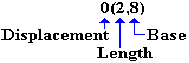
The displacement is 0 from the address X‘8058’, which is stored in R8. The object code is:
|
Type |
Bytes |
Operands |
1 |
2 |
3 |
4 |
5 |
6 |
|
SS(1) |
6 |
D1(L,B1),D2(B2) |
OP |
L |
B1 D1 |
D1D1 |
B2 D2 |
D2D2 |
|
|
|
|
D2 |
01 |
80 |
00 |
40 |
9F |
The instruction could have been written
as MVC
0(2,8),159(4), as the label
ASTERS is found at offset 159 (decimal) from the address in register 4.
The third example uses an explicit base and displacement representation of the destination address, with general–purpose register 8 serving as the explicit base register.
LA R8,PRINT GET ADDRESS PRINT INTO R8
MVC 60(2,8),ASTERS SPECIFY A DISPLACEMENT
Note the structure in the destination part of the source code, which is 60(2,8).
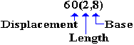
The displacement is 60 from the address X‘801C’, stored in R8. The object code is:
|
Type |
Bytes |
Operands |
1 |
2 |
3 |
4 |
5 |
6 |
|
SS(1) |
6 |
D1(L,B1),D2(B2) |
OP |
L |
B1 D1 |
D1D1 |
B2 D2 |
D2D2 |
|
|
|
|
D2 |
01 |
80 |
3C |
40 |
9F |
The instruction could have been written
as MVC
60(2,8),159(4), as the label
ASTERS is found at offset 159 (decimal) from the address in register 4.
Explicit Base Addressing for Packed Decimal Instructions
We now discuss a number of ways in which the operand addresses for character instructions may be presented in the source code. One should note that each of these source code representations will give rise to object code that appears almost identical. These examples are taken from Peter Abel [R_02, pages 273 & 274].
Consider the following source code, taken from Abel. This is based on a conversion of a weight expressed in kilograms to its equivalent in pounds; assuming 1kg. = 2.2 lb. Physics students will please ignore the fact that the kilogram measures mass and not weight.
ZAP POUNDS,KGS MOVE KGS TO POUNDS
MP
POUNDS,FACTOR
MULTIPLY BY THE FACTOR
SRP POUNDS,63,5
ROUND TO
KGS DC
PL3‘12.53’ LENGTH 3 BYTES
FACTOR DC
PL2‘2.2’ LENGTH 2 BYTES, AT
ADDRESSS KGS+3
POUNDS DS
PL5 LENGTH 5 BYTES, AT
ADDRESS KGS+5
The value produced is 12.53·2.2 = 27.566, which is rounded to 27.57.
The
instructions we want to examine in some detail are the MP and ZAP,
each of which
is a type SS instruction with source code format OP D1(L1,B1),D2(L2,B2). Each of the two operands in these
instructions has a length specifier.
In the
first example of the use of explicit base registers, we assign a base register
to
represent the address of each of the arguments.
The above code becomes the following:
LA R6,KGS ADDRESS OF LABEL KGS
LA R7,FACTOR ADDRESS
LA R8,POUNDS
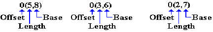
ZAP 0(5,8),0(3,6)
MP 0(5,8),0(2,7)
SRP 0(5,8),63,5
Each of the arguments in the MP and ZAP have the following form:
Recall the definitions of the three labels, seen just above. We analyze the instructions.
ZAP 0(5,8),0(3,6) Destination is at offset 0 from the address
stored in R8. The
destination has length 5 bytes.
Source
is at offset 0 from the address stored
in R6. The source has length 3 bytes.
MP 0(5,8),0(2,7) Destination
is at offset 0 from the address
stored in R8. The
destination has length 5 bytes.
Source
is at offset 0 from the address stored
in R7. The source has length 2 bytes.
But recall the order in which the labels are declared. The implicit assumption that the labels are in consecutive memory locations will here be made explicit.
KGS DC
PL3‘12.53’ LENGTH 3 BYTES
FACTOR DC
PL2‘2.2’ LENGTH 2 BYTES, AT
ADDRESSS KGS+3
POUNDS DS
PL5 LENGTH 5 BYTES, AT ADDRESS KGS+5
In this version of the code, we use the label KGS as the base address and reference all other addresses by displacement from that one. Here is the code.
LA R6,KGS ADDRESS OF LABEL KGS
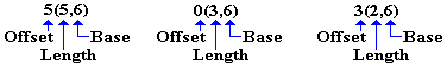
ZAP 5(5,6),0(3,6)
MP 5(5,6),3(2,6)
SRP 5(5,6),63,5
Each of the arguments in the MP and ZAP have the following form:
Recall the definitions of the three labels, seen just above. We analyze the instructions.
ZAP 5(5,6),0(3,6) Destination is at offset 5 from the address
stored in R6. The
destination has length 5 bytes.
Source
is at offset 0 from the address stored
in R6. The source has length 3 bytes.
MP 5(5,6),3(2,6) Destination
is at offset 5 from the address
stored in R6. The
destination has length 5 bytes.
Source
is at offset 3 from the address stored
in R6. The source has length 2 bytes.
In other
words, the base/displacement 6000 refers to a displacement of 0
from the address stored in register 6, which is being used as an explicit base
register for this operation. As
the address in R6 is that of KGS, this value represents the address KGS. This is the object code address generated in
response to the source code fragment 0(3,6).
The base/displacement 6003 refers to a displacement of 3 from the address stored in register 6, which is being used as an explicit base register for this operation. As the address in R6 is that of KGS, this value represents the address KGS+3, which is the address FACTOR. This is the object code address generated in response to the source code fragment 3(2,6).
The base/displacement 6005 refers to a displacement of 5 from the address stored in register 6, which is being used as an explicit base register for this operation. As the address in R6 is that of KGS, this value represents the address KGS+5, which is the address POUNDS. This is the object code address generated in response to the source code fragment 5(5,6).
It is worth notice, even at this point, that the use of a single register as the base from which to reference a block of data declarations is quite suggestive of what is done with a DSECT, also called a “Dummy Section”.