Sample: 4–to–1 MUX and 1–to–4 DEMUX
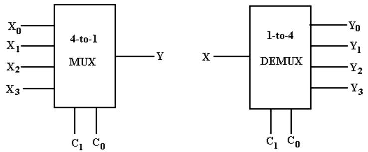
My Notation: X
for Input
C for Control
Signals
Y for Output
The Multiplexer Equation
Illustrated for a 4–to–1 MUX
Truth table Denote
the multiplexer output by M
|
C1 |
C0 |
M |
|
0 |
0 |
X0 |
|
0 |
1 |
X1 |
|
1 |
0 |
X2 |
|
1 |
1 |
X3 |
Equation Form
![]()
Here is another form of the
equation that is better when X is used as an input.
![]()
Build a 4–to–1 MUX
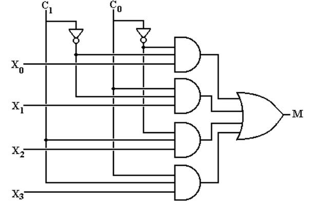
But what about an enable input for a multiplexer?
What does it mean for the output of the MUX to be
0?
Multiplexer Attached to a Bus Line
To control
a multiplexer’s connection to a common bus, we use a tri–state buffer and not
an enable input to the MUX. Here I use
“E” as the tri–state control.
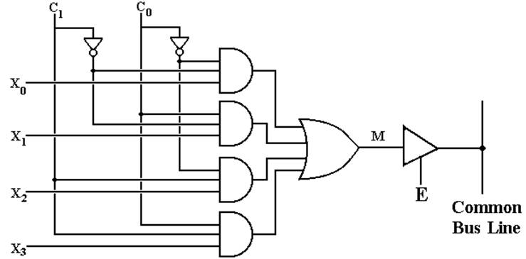
When E =
1, the selected MUX input is placed on the bus.
When E = 0, the MUX is detached from the bus; another source feeds the bus.
An Eight–to–One MUX in
Multi–Media
Here is
the circuit element selected in the Multi–Media Logic tool.
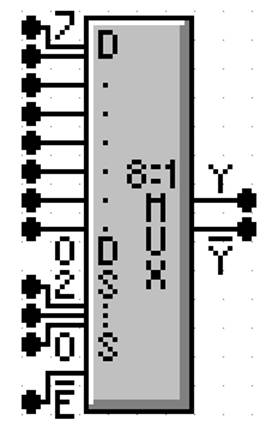
This is
an 8–to–1 MUX with inputs labeled 7 through 0, or equivalently X7
through X0. This is expected.
The
selector (control) lines are as expected; 2 through 0.
In my
notes, I use M for the output of the Multiplexer. This figure uses the symbol Y (not a problem)
and notes that real multiplexers also output the complement.
The only
issue here is the enable. Note that the
MUX is enabled low; this signal must be set to ground in order for the
multiplexer to function as advertised.
Commercial Multiplexer: Enabled
and Not Enabled
At top,
the output is X3. At bottom,
the output is 0.
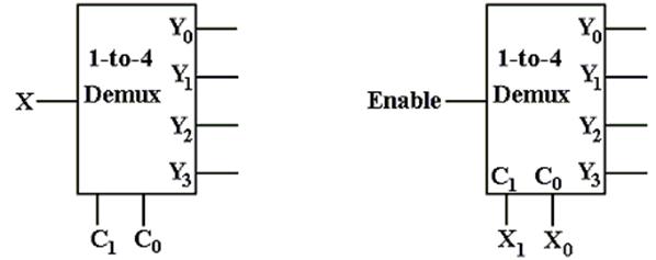
A 1–to–4 DEMUX
|
C1 |
C0 |
Selected Output |
|
0 |
0 |
Y0 = X Other outputs 0 |
|
0 |
1 |
Y1 = X Other outputs 0 |
|
1 |
0 |
Y2 = X Other outputs 0 |
|
1 |
1 |
Y3 = X Other outputs 0 |
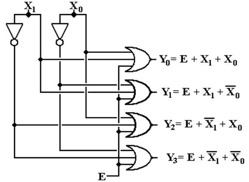
Build a 1–to–4 DEMUX
With an Enable
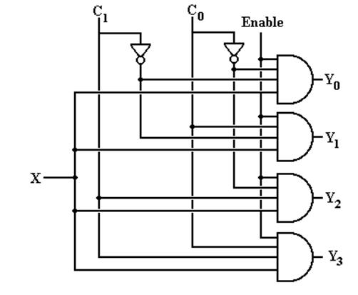
If Enable = 0, all outputs are 0.
Decoders
Decoders
interpret unsigned binary coding; they are N–to–2N devices.
Typical
examples include 2–to–4 decoders
3–to–8
decoders
4–to–16
decoders
Due
to the prevalence of decimal arithmetic, we also have 4–to–10 decoders.
These
are specialized 4–to–16 decoders with six fewer pins.
N–to–2N
decoders have N inputs, labeled X0,
X1, …., XN–1
2N
outputs, similarly labeled Y0, Y1, etc.
optionally,
an enable line.
Decoders
come in two varieties: active high and active low.
We
focus our lectures on active high
decoders:
the selected output goes to
logic 1
the outputs not selected
stay at logic 0.
Description
of a 3–to–8 Decoder
This
decoder has three inputs: X2, X1, X0
eight outputs: Y0, Y1, Y2,
Y3, Y4, Y5, Y6, Y7
Its
functioning is best described by a modified truth table.
|
X2 |
X1 |
X0 |
Action |
|
0 |
0 |
0 |
Y0 = 1, all
others are 0 |
|
0 |
0 |
1 |
Y1 = 1, all
others are 0 |
|
0 |
1 |
0 |
Y2 = 1, all
others are 0 |
|
0 |
1 |
1 |
Y3 = 1, all
others are 0 |
|
1 |
0 |
0 |
Y4 = 1, all
others are 0 |
|
1 |
0 |
1 |
Y5 = 1, all
others are 0 |
|
1 |
1 |
0 |
Y6 = 1, all
others are 0 |
|
1 |
1 |
1 |
Y7 = 1, all
others are 0 |
This
gives rise to the equations:
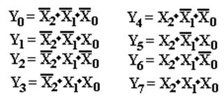
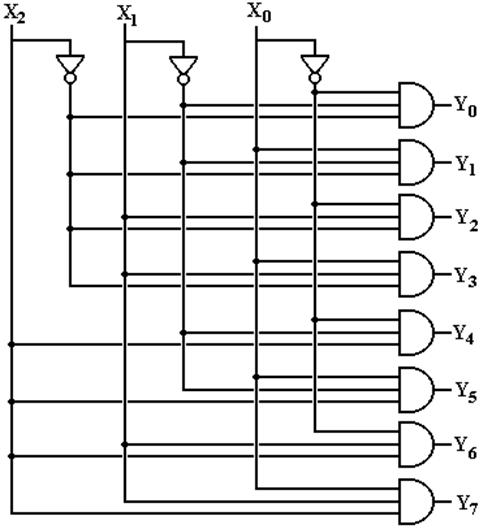
Circuit for
a 3–to–8 Decoder
This
follows from the equations.
The Enable
Input
Again,
in the above circuit one output will always be active.
Suppose
we want to have a decoder with no outputs active.
This
is the function of the enable input,
often denoted as “E”.
In
an enabled high decoder, when E = 0 no output is active
when
E = 1 the selected output is active
Here is the circuit diagram
for a 2–to–4 decoder with enable input.
Decoders: Circuit Symbols and Truth Tables
We
normally draw a decoder as a box, with inputs to the left and outputs to the
right. Note that the enable is drawn at
the bottom.
The
truth table for an active–high 2–to–4 decoder that is enabled high follows.
|
Enable |
X1 |
X0 |
|
Y0 |
Y1 |
Y2 |
Y3 |
|
0 |
d |
d |
|
0 |
0 |
0 |
0 |
|
1 |
0 |
0 |
|
1 |
0 |
0 |
0 |
|
1 |
0 |
1 |
|
0 |
1 |
0 |
0 |
|
1 |
1 |
0 |
|
0 |
0 |
1 |
0 |
|
1 |
1 |
1 |
|
0 |
0 |
0 |
1 |
The
“d” indicates that when Enable = 0, all outputs are 0 independent of X0,
X1
What Do the
Terms Mean?
Consider
a two–to–four decoder, with two inputs (X1 and X0).
1. Which output becomes active for a given input
pattern?
This is specified by the
definition of a decoder.
2. Does the active output go to logic high or
logic low?
For TTL, this is +5 volts or 0
volts.
3. How to manage the case in which no output should be active?
Active High
vs. Active Low
Here are two decoders.
One is active high and one is active low.
In each, output 2 has been selected.
In both circuits, we imagine each of the four outputs
as attached to a LED,
which illuminates when it is fed with a logic 1.
In the circuit at left, only the selected output
illuminates its LED.
It is active high.
In the circuit at right, every output but the selected
output illuminates its LED.
It is active low.
In many circuits, active low appears to be the
preferred mode.
Active–Low,
Enabled–Low Two–to–Four Decoder
Here is a truth table for this circuit.
|
Enable |
X1 |
X0 |
Y0 |
Y1 |
Y2 |
Y3 |
|
1 |
d |
d |
1 |
1 |
1 |
1 |
|
0 |
0 |
0 |
0 |
1 |
1 |
1 |
|
0 |
0 |
1 |
1 |
0 |
1 |
1 |
|
0 |
1 |
0 |
1 |
1 |
0 |
1 |
|
0 |
1 |
1 |
1 |
1 |
1 |
0 |
If
Enable = 1, all outputs are 1.
If Enable = 0, then the input (X1X0)
selects the output that is enabled.
Here are the equations for the circuit. Here the enable is denoted by “E”.
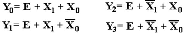
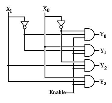
Circuit for
the Enabled–Low, Active–Low
Two–to–Four Decoder
Here it is. “E”
denotes the enable input, but is not properly labeled
as “enable low”. I wanted the circuit
to be a bit simple.
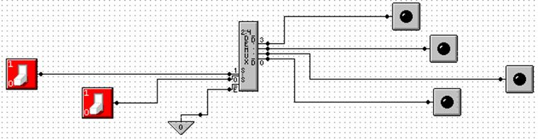
Where are
the Decoders?
One will note that the Multi–Media Logic tool does not
provide a decoder circuit. Fortunately,
a 1–to–2N demultiplexer can be made into an N–to–2N
decoder.
Look at the circuit to the left. The control signals C1,C0 select the output
to receive the input X. This is exactly
equivalent to a decoder.
In
the circuit at right, the selected output gets the input, now called “Enable”.
For the demultiplexers we use, the other outputs get a logic 1.
We
can fabricate an active low decoder.
The MUX as
an Active–Low Decoder
Here
is the 2–to–4 Demultiplexer as an 2–to–4 active low decoder.
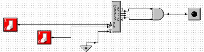
Here
is an answer to one of the homework problems: use a 2–to–4 decoder for
XOR. The function is either S(1, 2) or P(0, 3).
Circuit
Simulation Results
Enabled,
Input 2 Not Enabled
Here we see a composite of two screen shots from
Multimedia Logic.
At left, the decoder is enabled and input 2 is
selected.
The selected output is logic 0.
All other outputs are logic 1.
At right, the decoder is not enabled. All outputs are logic 1.