Some
Sample Sums, with Comments
We begin with two simple sums, each involving only
single digits.
2 + 2 = 4, and 5 + 5 = 10.
If these are so, why do we write the
following sum 25 + 25 as
25 + 25 = 50, and not as
25 + 25 = 4 10? What
digit is written in the unit’s column of the sum?
The reason that we do not do this is the idea of a
carry from the unit’s
column to the ten’s column.
In the language of the second grade, we describe the
addition as follows:
1. 5 + 5 is 0, with a carry–out of 1, which
goes into the ten’s column.
2. 2 + 2 is 4, but we have a carry–in of 1 from
the unit’s column,
so
we say 2 + 2 + 1 = 5. The sum digit in
this column is a 5.
Positional
Notation in Arithmetic
In standard decimal arithmetic, the number 25 is
read as “twenty five”, and
represents 2 · 10 + 5 · 1: two tens plus five ones.
Remember that the only digits used in binary numbers
are 0 and 1.
In binary arithmetic, the number 10 is read as “one
zero”, avoiding the
names we use for decimal numbers. It
represents 1 · 2 + 0 · 1.
In binary arithmetic, the number 101 represents 1·22 + 0·21 + 1·1, or
1·4 + 0·2 + 1·1
= 4 + 1 = 5.
In all arithmetics: 0 + 0 = 0,
0 + 1 = 1, and
1
+ 0 = 1.
In decimal arithmetic: 1 + 1 = 2.
In binary
arithmetic what is 1 + 1?
The Sum 1 + 1 in Binary
Arithmetic
We have just noted that the decimal number 2 is
represented in binary as 10.
It must be the case that, in binary addition, we
have the sum as
1
+ 1 = 10
This reads as “the addition 1 + 1 results in a sum
of 0 and a carry–out of 1”.
Recall the decimal sum 25 + 25.
1
2 5
2 5
5 0
The 1 written above the numbers in the ten’s column
shows the carry–out
from the unit’s column as a carry–in to the ten’s column.
The
Half Adder
The half adder takes two single bit binary numbers
and produces
a sum and a carry–out, called “carry”.
Here is the truth table description of a half
adder. We denote the sum A + B.
|
A |
B |
Sum |
Carry |
|
0 |
0 |
0 |
0 |
|
0 |
1 |
1 |
0 |
|
1 |
0 |
1 |
0 |
|
1 |
1 |
0 |
1 |
Written as a standard sum, the last row represents
the following:
01
+ 01
10
The sum column
indicates the number to be written in the unit’s column,
immediately below the two 1’s. We write
a 0 and carry a 1.
The Half Adder and the
Full Adder
In all versions of
arithmetic, including binary and decimal, the half adder
represents what we do for the unit’s column when we add integers.
There is no possibility of a carry–in for the unit’s
column, so we do not design
for such. Another way is to say that
there is a carry–in; it is always 0.
The full adder in decimal arithmetic would be used
for the other columns:
the ten’s column, the hundred’s column, and so on.
For these columns, a non–zero carry–in is a distinct
possibility
Considered this way, we might write our sums table
as follows.
2 + 2 = 4, if the carry–in is 0,
and
2 + 2 = 5, when the carry–in is 1.
Admittedly, the complexities of decimal arithmetic
suggest another way,
just add the values as three numbers, here 2 + 2 + 1 = 5.
Implementing
the Half Adder
Here again is the truth table for the half adder.
|
A |
B |
Sum |
Carry |
|
0 |
0 |
0 |
0 |
|
0 |
1 |
1 |
0 |
|
1 |
0 |
1 |
0 |
|
1 |
1 |
0 |
1 |
We need equations for each of the Sum
and Carry. Because we have used a
truth table to specify these functions, we consider Boolean expressions.
Note that the carry is the logical AND of the two
inputs: Carry = A·B.
The sum can be given in two equivalent expressions.
The simplest expression uses the exclusive OR function: Sum = AÅB.
An equivalent expression in terms of the basic AND, OR, and NOT is:
![]()
Circuits
for the Half Adder
Here are two slightly different circuit
implementations of the half adder.
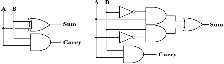
The circuit on the left implements the sum function
as Sum = AÅB.
The circuit on the right implements the sum function
as
![]()
Implementing
the Full Adder
Here we show the truth table for the sum of A and B,
with carry–in of C.
|
A |
B |
C |
Sum |
Carry |
|
0 |
0 |
0 |
0 |
0 |
|
0 |
0 |
1 |
1 |
0 |
|
0 |
1 |
0 |
1 |
0 |
|
0 |
1 |
1 |
0 |
1 |
|
1 |
0 |
0 |
1 |
0 |
|
1 |
0 |
1 |
0 |
1 |
|
1 |
1 |
0 |
0 |
1 |
|
1 |
1 |
1 |
1 |
1 |
To read this as decimal, pretend that
the Sum is “Sum_Bit” and read as
the Decimal_Sum = Carry·2
+ Sum_Bit.
So 1 + 1 + 0
= 1·2 + 0 = 2 (decimal), and
1 + 1 + 1 = 1·2 + 1 = 3
(decimal).
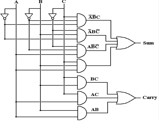
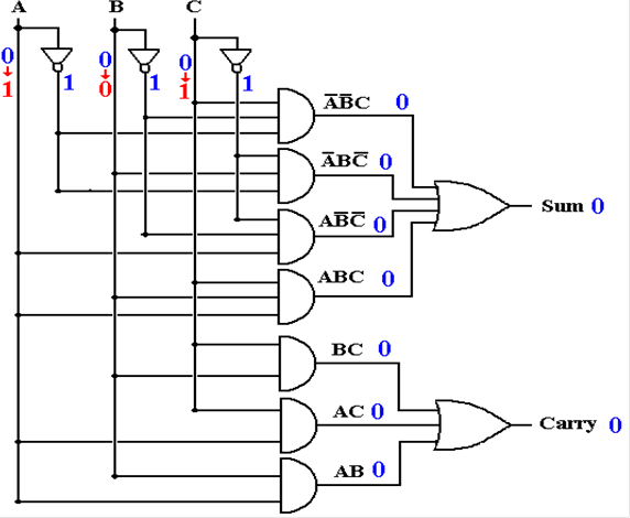
One
Circuit for the Full Adder
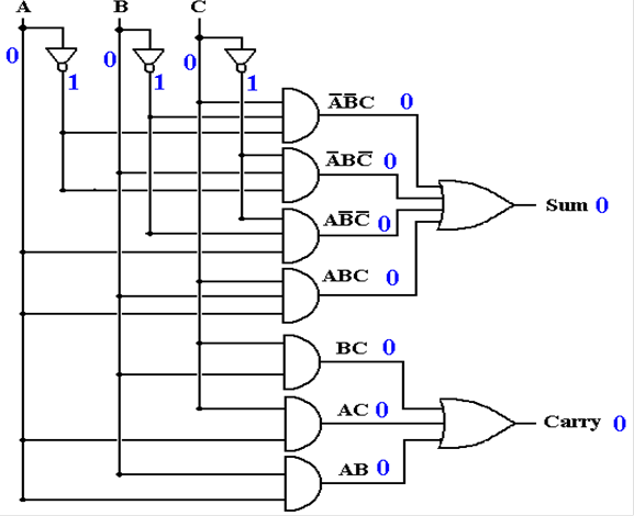
Here is the traditional AND/OR implementation of the
full adder.
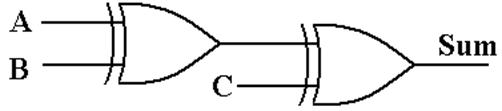
Another
Circuit for the Full Adder
The slide above gave the standard design of a full
adder with a grouping of
AND gates followed by an OR gate. Here
is another implementation of the
SUM function using exclusive OR.
|
A |
B |
C |
(A Å
B) |
(A Å
B) Å C |
|
0 |
0 |
0 |
0 |
0 |
|
0 |
0 |
1 |
0 |
1 |
|
0 |
1 |
0 |
1 |
1 |
|
0 |
1 |
1 |
1 |
0 |
|
1 |
0 |
0 |
1 |
1 |
|
1 |
0 |
1 |
1 |
0 |
|
1 |
1 |
0 |
0 |
0 |
|
1 |
1 |
1 |
0 |
1 |
The
Full Adder with C = 0
The circuit above implements the following two
expressions, where C is
the carry–in to the full adder.
Sum = ![]() ·
·![]() ·C
+
·C
+ ![]() ·B·
·B·![]() +
A·
+
A·![]() ·
·![]() +
A·B·C
+
A·B·C
Carry = A·B + A·C
+ B·C
Suppose we let the carry–in C = 0. Then ![]() = 1.
= 1.
What we have then is as follows.
Sum = ![]() ·
·![]() ·0
+
·0
+ ![]() ·B·1 + A·
·B·1 + A·![]() ·1
+ A·B·0
·1
+ A·B·0
= ![]() ·B
+ A·
·B
+ A·![]()
Carry = A·B + A·0
+ B·0
= A·B
As expected, a full adder with carry–in set to zero
acts like a half adder.
The
Full–Adder and Half–Adder as Circuit Elements
When we build circuits with full adders or half
adders, it is important to focus
on the functionality and not on the implementation details.
For this reason, we denote each circuit as a simple
box with inputs and outputs.
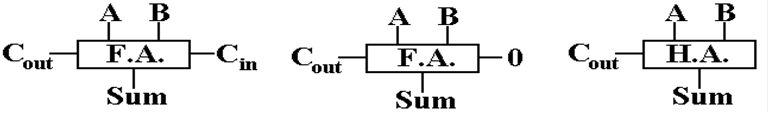
The figure on the left depicts a full–adder with
carry–in as an input.
The figure on the right depicts a half–adder with no
carry–in as input.
The figure in the middle depicts a full–adder acting
as a half–adder.
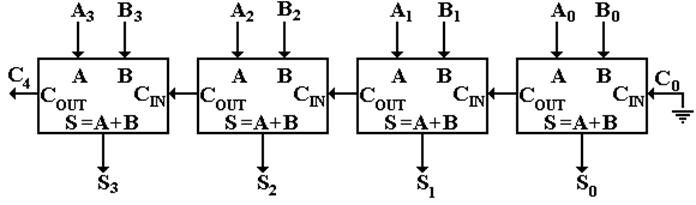
A
Four–Bit Full–Adder
Here is a depiction of a four–bit full adder to add
two binary numbers,
depicted as A3A2A1A0 and B3B2B1B0.
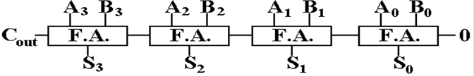
Note that the carry–out from the unit’s stage is
carried into the two’s stage.
In general, the carry is propagated from right to left, in the same manner as
we see in manual decimal addition. This
is called a “ripple carry adder”.
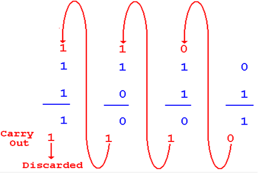
Here is an example of its output. The 4–bit sum is truncated to 1001.
1110
+ 1011
11001
Note that the unit’s adder is implemented using a
full adder.
Propagating
the Carry Bits
Just as in standard arithmetic, when done by hand,
the carry of one stage
is propagated as a carry–in to the next higher stage.
Addition
and Subtraction
In order to convert a ripple–carry adder into a
subtractor, we employ
the standard algebra trick: A – B is the same as A + (–B).
In order to subtract B from A, it is necessary to
negate B to produce
–B, and then to add that number to A.
We now have to develop a circuit that will negate a
binary value.
In order to do this, we must stipulate the method
used to represent
signed integers. As in earlier lecture,
we use two’s–complement notation.
In this method, in order to negate a binary integer,
it is necessary to
produce the two’s–complement of that value.
1. First,
take the one’s–complement of the binary integer, and then
2. Add 1 to that value.
We have to develop a circuit to create the
one’s–complement of a binary
integer. We shall develop two circuits
to do this.
The
One’s Complement of a Binary Integer
In order to take the one’s–complement of an integer
in binary form, just
change every 0 to a 1, and every 1 to a 0.
Here are some examples.
Original value 0110 0111 1010 0011
One’s complement 1001 1000 0101 1100
The circuit that does this conversion is the NOT
gate. The circuit below
would be used for four–bit integers.
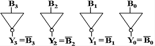
If the input is B3B2B1B0
= 0110, the output is Y3Y2Y1Y0 =
1001.
This circuit can be extended to any number of bits
required.
The
XOR Gate as a NOT Gate
In order to make an adder/subtractor, it is
necessary to use a gate that can
either pass the value through or generate its one’s–complement.
The exclusive OR gate, XOR, is exactly what we need.
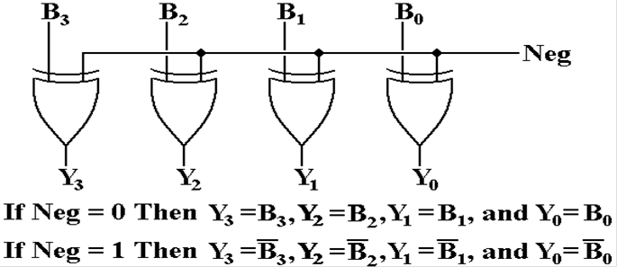
This is controlled by a single binary signal: Neg.
Let B = 1011.
If Neg = 0, then Y = 1011. If Neg
= 1, then Y = 0100.
Some
Notation for Bit–Wise Operations
Taking
the one’s–complement of a binary integer involves taking the
one’s–complement of each of its bits. We
use the NOT notation to
denote the one’s–complement of the entire integer.
If
B = B3B2B1B0 is a four–bit binary
number, its one’s–complement is
![]() .
.
Remember that to get the two’s–complement, one takes
the one’s–complement
and adds one. In two’s–complement arithmetic
we have: ![]() .
.
This suggests the use of an adder to produce the
negative. For B = B3B2B1B0,
we take the one’s complement to start the negation process. The addition of 1,
necessary to take the two’s–complement, is achieved by setting the carry–in of
the unit’s full–adder to 1.
This
is the reason for using a full–adder in the unit’s position. We can alternate
between an adder and subtractor. More on
this a bit later.
The
Negator Circuit
Here
is the circuit to produce the negative of a 4–bit number B = B3B2B1B0.
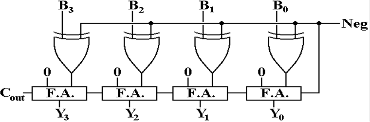
If Neg = 0, then the XOR gates pass the values B3B2B1B0 unchanged and
the ripple–carry adder adds 0 to that.
The result is Y = B.
If Neg = 1, then the XOR gates cause the
one’s–complement of B = B3B2B1B0
to be computed.
Note that the carry–in of the full adder is set to 1, so that it
adds 1 to the one’s–complement, thus producing the negative: Y = – B.
The
Full Adder/Subtractor
We now have the circuit that either adds or
subtracts. This is a 4–bit circuit
that produces either (A + B) or (A – B).
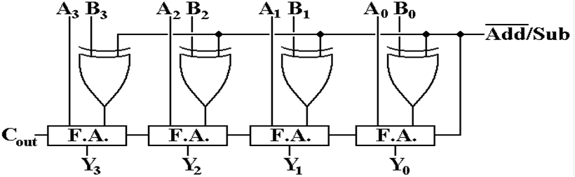
![]()
This
notation is used for a two–valued control signal. When the value is 0, the
circuit is to add, when it is 1 the circuit is to subtract.
This
adder/subtractor can be extended to any number of binary bits.
Overflow: “Busting the Arithmetic”
The range of 16–bit two’s–complement
arithmetic is
–
32,768 to 32,767
Consider the following addition
problem: 24576 + 24576.
Now + 24,576 (binary 0110 0000 0000 0000) is well within the range.
0110
0000 0000 0000 24576
0110 0000 0000 0000 24576
1100 0000 0000 0000 – 16384
What happened?
We had a carry into the sign
bit. This is “overflow”. The binary representation
being used cannot handle the
result.
NOTE: This works as unsigned arithmetic.
24,576 + 24,576 = 49,152 =
32768 + 16384.
Detecting Overflow
For
addition, overflow occurs in only two situations:
1) Two
positive integers are added and the result is negative.
2) Two
negative integers are added and the result is positive.
Consider
the 16–bit examples shown above.
Remember that the bits are numbered
left to right as 15 down to 0, with bit 15 being the sign bit for signed
representations.
Look
at the full adder responsible for adding the sign bit for two integers: A and B.
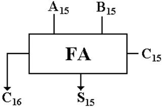
The overflow condition is now: A15
== 0, B15 == 0, and S15 ==1,
or
A15 == 1,
B15 == 1,
and S15 ==0.
Implementing
the Detector
Here we show the truth table for the sign bit.
|
A15 |
B15 |
C15 |
S15 |
C16 |
|
0 |
0 |
0 |
0 |
0 |
|
0 |
0 |
1 |
1 |
0 |
|
0 |
1 |
0 |
1 |
0 |
|
0 |
1 |
1 |
0 |
1 |
|
1 |
0 |
0 |
1 |
0 |
|
1 |
0 |
1 |
0 |
1 |
|
1 |
1 |
0 |
0 |
1 |
|
1 |
1 |
1 |
1 |
1 |
Rows 1 and 6 are the only two rows in
which overflow occurs. These two
rows share one interesting property: C15 ¹ C16, or C15 Å C16 = 1.
The use of this property allows overflow
to be detected efficiently.
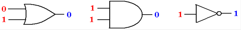
Gate Delays
Consider three gates, each of which
has input that has not changed for
some time. The output of each gate
correctly implements its Boolean function.
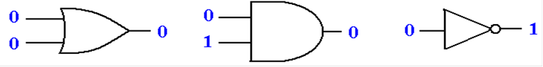
We now consider what happens as the
input to each gate is changed
suddenly. Note that the output does not
change at the same time as the input.
For a short time, called a “hazard”,
the output of the gate is not that
of the Boolean function supposedly implemented.
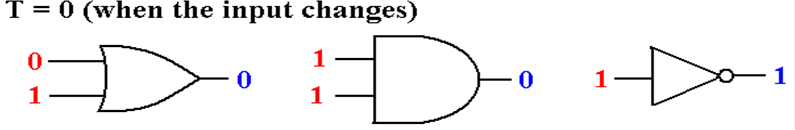
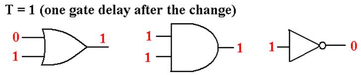
Gate Delays (More)
For the time duration of one gate
delay, the outputs do not match the inputs.
After one gate delay (about 2 to 10
nanoseconds) the output is correct.
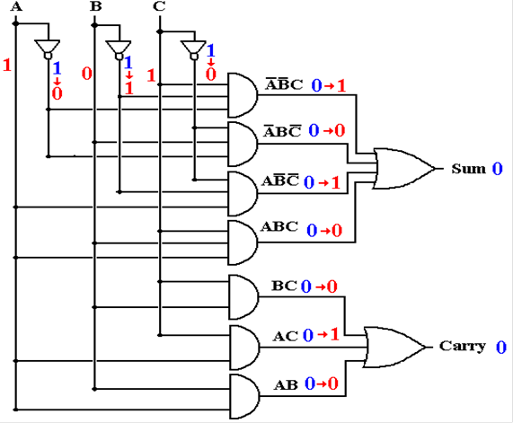
Full Adder with Gate Delays (Before
Input Changes)
Assume the inputs have been stable
for some time.
Full Adder with Gate Delays (Input
Changes at T = 0)
At this point, no outputs are
correct.
Full Adder with Gate Delays (T = 1)
Some output is correct, but the
upper AND gates are reacting to input at T = 0.
Full Adder with Gate Delays (T = 2)
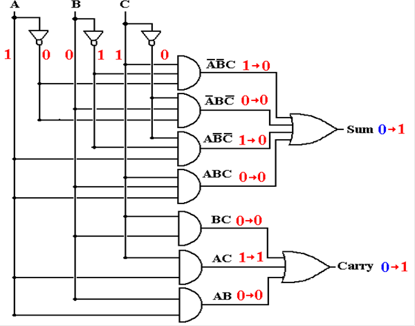
The carry out is correct, but the
sum out is reacting to input at T = 1.
Full Adder with Gate Delays (T = 3)
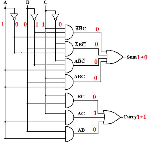
At T = 3 (and later), all output is
correct.
The Ripple–Carry Adder
Carry–in
to stage K (bit K) is valid at T = 2·K.
Carry–out
from stage K is valid at T = 2·K + 2.
Sum from
stage K is valid at T = 2·K + 3.
32–bit
sum valid after stage 31 finishes (65 gate delays)
This circuit is not used in commercial computers.