The System
Bus
The
System Bus is one of the four major components of a computer.
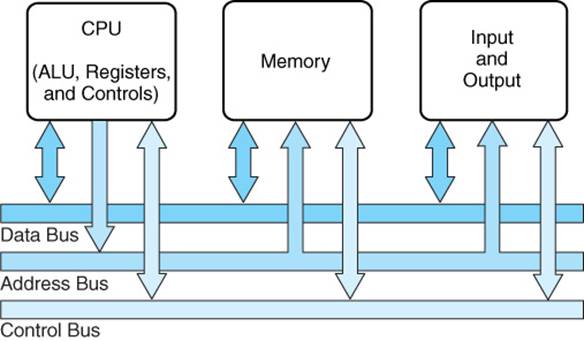
This
logical representation is taken from the textbook.
The
system bus is used by the other major components to communicate
data, addresses, instructions, and control signals.
Real computers have more than
one bus, but this is all we need.
Notation for
Bus Signal Levels
The system clock is represented as a trapezoidal wave
to emphasize the fact
that it does not change instantaneously.
Here is a typical depiction. Others may be seen, but this is what our
author uses.
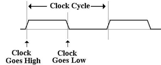
Single control signals are depicted in a similar
fashion, except (of course) that they
may not vary in “lock step” with the bus clock.
Notation for
Multiple Signals
A single control signal is either low or high (0 volts
or 5 volts).
A collection, such as 32 address lines or 16 data
lines cannot be represented with
such a simple diagram. For each of
address and data, we have two important states
address or data is valid
address or data is not valid
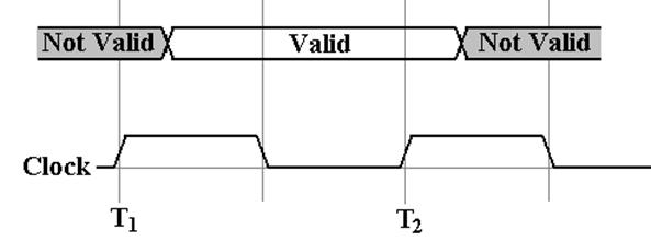
For example, consider the address lines on the
bus. Imagine a 32–bit address.
At some time after T1, the CPU asserts an
address on the address lines. This means
that each of the 32 address lines is given a value.
When the CPU has asserted the address, it is valid
until the CPU ceases assertion.
Reading Bus
Timing Diagrams
Sometimes,
we need to depict signals on a typical bus.
Here we are looking at a
synchronous bus, of the type used
for connecting memory.
This
figure, taken from the textbook, shows the timings on a typical bus.
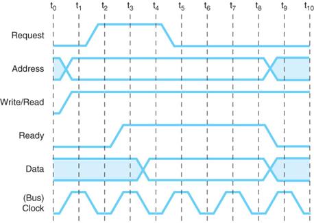
Note
the form used for the Address Signals: between t0 and t1
they change value.
According to the figure, the address signals remain valid from t1
through the end of t7.
Attaching an
I/O Device to a Bus
This
figure shows a DMA Controller for a disk attached to a bus.
It is only slightly more complex than a standard controller.
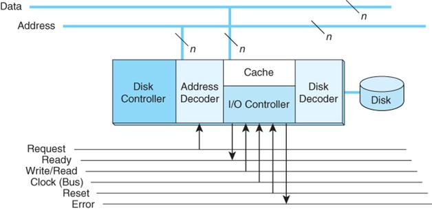
Each
I/O Controller has a range of addresses to which it will respond.
Specifically,
the device has a number of registers, each at a unique address.
When
the device recognizes its address, it will respond to I/O commands sent
on the command bus.
Bus
Arbitration
A number of I/O devices are usually connected to a
bus.
Each I/O device can generate an Interrupt, called “INT”
when it needs service.
The CPU will reply with an acknowledgement,
called “ACK”.
The handling by the CPU is simple. There are two signals only
INT some
device has raised an interrupt
ACK the
CPU is ready to handle that interrupt.
We need an arbitrator to take the ACK and pass it to
the correct device.
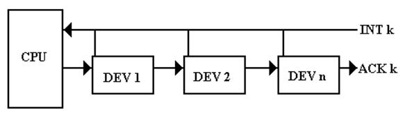
The common architecture is to use a “daisy chain”, in which the ACK is
passed
from device to device until it reaches the device that raised the interrupt.
Northbridge
and Southbridge
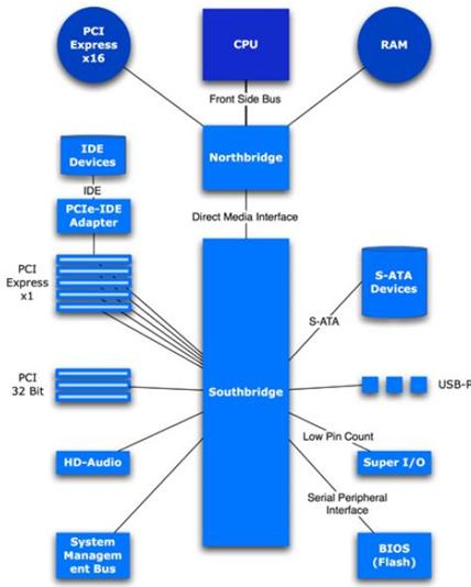
In modern computers, the requirement to
manage I/O devices with a wide range of
data capacities has driven a new design.
This design has two controller hubs, called
“Northbridge” and “Southbridge”.
The Northbridge handles the faster devices
such as memory and graphics.
The Southbridge handles slower devices,
and communicates with the CPU through
the Northbridge.
The DASD and
Evolution of Storage Devices
Rule
1: “Data processing requires data
storage”. – I just made that up.
Data
were originally stored on paper media, first as written documents but fairly
soon
(Hollerith, late 19th century) the storage medium was
machine–readable.
In
the 1950’s, New York Life Insurance Company was devoting an entire floor
of its main building to the storage of punched cards. Something had to change.
IBM
quickly came out with two magnetic media for storing data
the magnetic tape
the DASD (disk)
The
acronym “DASD” stands for Direct Access Storage Device.
Until
recently, the standard disk drive was the only commercially viable example.
We
now have another very popular example, these USB “flash drives”. While
different from standard disk drives, these are managed as if they were disk
drives
and are considered disk drives.
Structure of
a Large Disk Drive
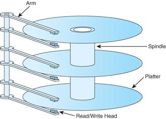
The
typical large–capacity (and physically small) disk drive has a number of
glass platters with magnetic coating.
These spin at a high rate (7,200 rpm
or 120 / second)
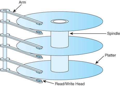
This
drawing shows a disk with three platters and six surfaces. In general,
a disk drive with N platters will have 2·N surfaces, the top and bottom
of each platter.
On
early disk drives, before the introduction of sealed drives, the top and
bottom surfaces would not be used because they would become dirty.
More on Disk
Drive Structure
Each
surface is divided into a number of concentric tracks.
Each
track has a number of sectors.
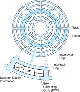
A
sector usually contains 512 bytes of data, along with a header and trailer
part.
Seek Time
and Rotational Latency
In
order to read from a disk track, the read/write heads must be moved to the
track.
This
is a mechanical action, as the read/write heads are physical devices.
There
are two seek times typically quoted for a disk.
Track–to–track: the time to move the heads to the next track
over
Average: the average time to move the
heads to any track.
The
rotational delay is due to the fact
that the disk is spinning at a fixed high speed.
It takes a certain time for a specific sector to rotate under the read/write
heads.
Suppose
a disk rotating at 12,000 RPM. That is
200 revolutions per second.
Each sector moves under the read/write heads 200 times a second,
once every 0.005 second or every 5 milliseconds.
The
rotational latency, or average rotational
delay, is one half of the time for a
complete revolution of the disk. Here it
would be 2.50 milliseconds.
The Idea of
a Cylinder
Fixed head disks have one head per track. The last time I heard of such a
device was 1977, when working with a 1 MB fixed head disk on a PDP–11/45.
I
claim that fixed head disks are obsolete.
Revisit the picture of a typical disk.
Question:
How many tracks can be read before the read/write heads must be moved?
Answer:
One track per surface can be read without moving the heads. Here it is 6.
Definition: A cylinder
is that set of tracks that can be read without moving the disk
read write heads. A disk has as many cylinders as a surface has
tracks.
A cylinder has as many tracks as
the disk has surfaces.