Other Small Scale Integration
Circuits
In this lecture, we
discuss two of the more common SSI (Small Scale
Integrated) circuits: the Decoder and the Multiplexer.
These are combinational
circuits built from the basic logic gates, which are
AND, OR, NOT, and XOR.
These SSI chips allow
us to specify our design at a higher level, thus
focusing on the function of a circuit and not its basic implementation.
The building blocks
that we discuss today are as follows:
The
decoder, which can be viewed as
producing the unsigned decimal
equivalent of a binary code with a fixed number of bits.
The
multiplexer, which selects one of a
number of inputs and passes it
to the output.
The tuner on a standard
TV functions as a multiplexer, selecting one of the
incoming number of channels and passing it to the
display circuitry.
Review of Binary Codes
These devices are based on binary coded
input. We review simple binary codes
that would be used on smaller decoders and multiplexers.
2–bit codes: 00 0 3–bit codes: 000 0
01 1 001 1
10 2 010 2
11 3 011 3
100 4
101 5
110 6
111 7
The 4–bit codes are
simply the unsigned binary representation of 0 – 15.
0000 is 0, 0001 is 1, 0010 is 2, 0011
is 3,
0100 is 4, 0101 is 5, 0110 is 6, 0111
is 7,
1000 is 8, 1001 is 9, 1010 is 10, 1011
is 11,
1100 is 12, 1101 is 13, 1110 is 14, 1111
is 15.
Decoders
Decoders are the opposite of encoders; they
are N–to–2N devices.
Typical examples include 2–to–4 decoders
3–to–8
decoders
4–to–16
decoders
Due to the prevalence of decimal arithmetic,
we also have 4–to–10 decoders.
These are specialized 4–to–16 decoders with
six fewer pins.
N–to–2N decoders have N inputs, labeled X0, X1, …., XN–1
2N outputs, similarly labeled Y0, Y1,
etc.
optionally, an enable line.
Decoders come in two varieties: active high
and active low.
We focus our lectures on active high decoders:
the selected output goes to
logic 1
the outputs not selected
stay at logic 0.
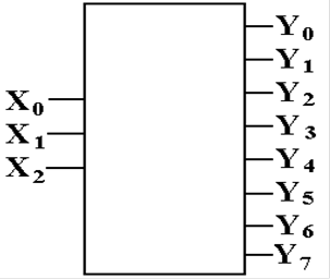
A 3–to–8 Decoder (Simple View)
Here is the symbol that
might be used to represent a 3–to–8 decoder.
It is a bit simplistic in that it leaves out several important features.
The binary input
selects the one output that is to be active.
All other
outputs are inactive.
 If
X2 = 1, X1 = 0, X0 = 1, then Y5 is
the
If
X2 = 1, X1 = 0, X0 = 1, then Y5 is
the
selected output to be active. All other
outputs are not active.
In a similar fashion,
each of the 8 possible
binary codes activates exactly one of the
outputs, with all others not active.
Small decoders (2–to–4,
3–to–8, and 4–to–16) are often used in
digital design work.
Description of a 3–to–8 Decoder
This decoder has three inputs: X2,
X1, X0
eight outputs: Y0, Y1, Y2,
Y3, Y4, Y5, Y6, Y7
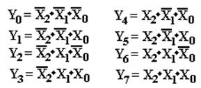
Its functioning is best described by a
modified truth table.
|
X2 |
X1 |
X0 |
Action |
|
0 |
0 |
0 |
Y0 = 1,
all others are 0 |
|
0 |
0 |
1 |
Y1 = 1,
all others are 0 |
|
0 |
1 |
0 |
Y2 = 1,
all others are 0 |
|
0 |
1 |
1 |
Y3 = 1,
all others are 0 |
|
1 |
0 |
0 |
Y4 = 1,
all others are 0 |
|
1 |
0 |
1 |
Y5 = 1,
all others are 0 |
|
1 |
1 |
0 |
Y6 = 1,
all others are 0 |
|
1 |
1 |
1 |
Y7 = 1,
all others are 0 |
This gives rise to the equations:
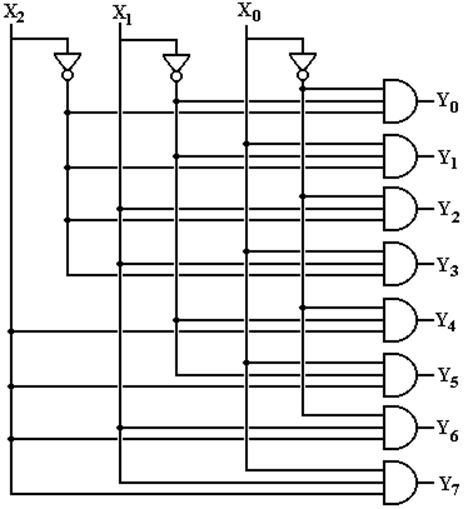
Circuit for a 3–to–8 Decoder
This follows from the equations.
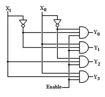
The Enable Input
Again, in the above circuit one output will
always be active.
Suppose we want to have a decoder with no
outputs active.
This is the function of the enable input, often denoted as “E”.
In an enabled high decoder, when E = 0 no
output is active
when E = 1 the
selected output is active
Here is the circuit
diagram for a 2–to–4 decoder with enable input.
Multiplexers
and Demultiplexers
Multiplexer
– MUX
Associates One of Many Inputs to a
Single Output
Demultiplexer
– DEMUX
Associates One Input with One of
Many Outputs
Circuit Inputs Control Outputs
Signals
Multiplexer 2N N 1
Demultiplexer 1 N 2N
Sample:
4–to–1 MUX and 1–to–4 DEMUX
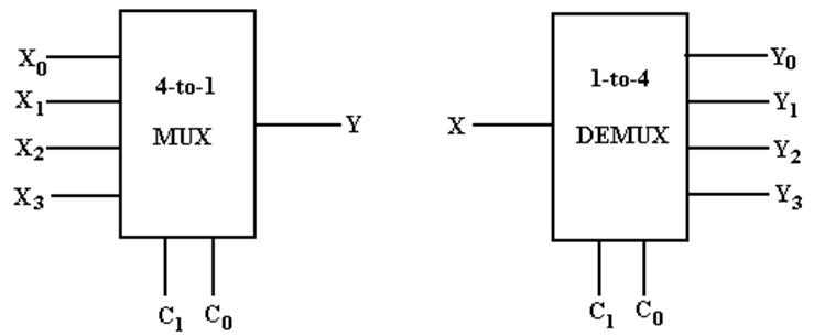
My Notation: X for Input
C for Control
Signals
Y for Output
The
Multiplexer Equation
Illustrated for a 4–to–1 MUX
Truth table Denote the multiplexer output by M
|
C1 |
C0 |
M |
|
0 |
0 |
X0 |
|
0 |
1 |
X1 |
|
1 |
0 |
X2 |
|
1 |
1 |
X3 |
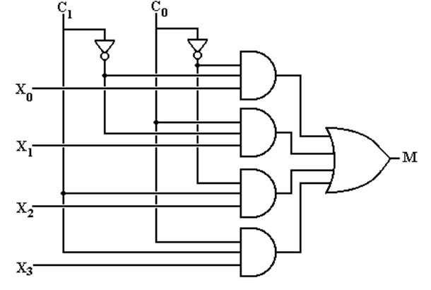
Equation Form
![]()
Here
is another form of the equation that is better when X is used as an input.
![]()
Build
a 4–to–1 MUX
But what
about an enable input for a multiplexer?
What does
it mean for the output of the MUX to be 0?
Build
a 1–to–4 DEMUX
With an Enable
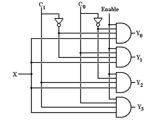
If Enable = 0, all outputs are 0.